Electronic Circuits: Fundamentals and Applications 3rd Edition — A Practical Engineering Guide for Students and Professionals
Introduction ⚡
Electronic circuits are the foundation of almost every modern electrical and electronic system. From smartphones and computers to industrial controllers, medical instruments, automotive systems, communication equipment, and renewable-energy technologies, electronic circuits provide the mechanisms required to process, control, amplify, switch, convert, and transmit electrical signals.
The engineering study of electronic circuits begins with relatively simple components such as resistors, capacitors, inductors, diodes, and transistors. As these elements are combined, they form increasingly sophisticated functional blocks such as amplifiers, filters, oscillators, rectifiers, voltage regulators, logic circuits, and embedded-control systems.
Electronic Circuits: Fundamentals and Applications, 3rd Edition by Mike Tooley is positioned as a practical reference combining fundamental electronics with applications. The third edition includes areas such as amplifiers, logic circuits, power supplies, oscillators, circuit construction, fault finding, circuit simulation, electronic CAD, and PIC microcontrollers.


The central engineering idea is simple:
Electrical components + mathematical principles + practical design = functional electronic system.
This article develops that idea from beginner concepts to practical engineering applications. 🔧
Background Theory
Electronic circuit analysis is built upon several fundamental electrical quantities:
- Voltage, (V) — electrical potential difference, measured in volts (V).
- Current, (I) — movement of electric charge, measured in amperes (A).
- Resistance, (R) — opposition to current, measured in ohms (Ω).
- Power, (P) — rate of electrical energy transfer, measured in watts (W).
- Capacitance, (C) — ability to store electrical energy in an electric field.
- Inductance, (L) — ability to store energy in a magnetic field.
One of the most important relationships is Ohm’s law:
From this equation:
and
Electrical power can be expressed as:
Using Ohm’s law, engineers can also write:
or
These equations are not merely theoretical. They allow engineers to select component ratings, calculate circuit currents, estimate heat generation, and determine whether a design can operate safely.
Kirchhoff’s Laws
Two principles are particularly important when analyzing larger circuits.
Kirchhoff’s Current Law (KCL) states that the algebraic sum of currents entering and leaving a node is zero:
Kirchhoff’s Voltage Law (KVL) states that the algebraic sum of voltages around a closed loop is zero:
Together with component equations, these laws provide a foundation for analyzing complex electronic networks.
Analog and Digital Electronics
Electronic circuits are commonly divided into two broad categories.
Analog circuits operate with continuously varying voltages or currents. Examples include:
- Audio amplifiers
- Sensor interfaces
- Filters
- Oscillators
- Voltage regulators
Digital circuits primarily process discrete logic states, commonly represented as LOW and HIGH.
Examples include:
- Logic gates
- Counters
- Microcontrollers
- Digital memory
- Computer processors
Modern products frequently combine both approaches. A temperature sensor, for example, may produce an analog signal that is conditioned by an analog circuit and then converted into digital data by an ADC.
Definition: What Is an Electronic Circuit? 🔌
An electronic circuit is an interconnected arrangement of electrical and electronic components designed to perform a specific function by controlling the flow of electrical energy or electrical signals.
A circuit normally requires:
- A source of electrical energy.
- Conductive paths.
- Components that control or transform electrical behavior.
- A defined functional purpose.
The components can be passive or active.
Passive Components
Passive components do not normally provide power gain.
Common examples include:
- Resistors
- Capacitors
- Inductors
- Transformers
A resistor may limit current, a capacitor may store charge or block DC while passing changing signals, and an inductor may oppose rapid changes in current.
Active Components
Active devices can control current or voltage and may provide amplification or switching.
Examples include:
- Bipolar junction transistors (BJTs)
- MOSFETs
- Operational amplifiers
- Integrated circuits
- Microcontrollers
The transistor is particularly important because it can function as an amplifier or electronic switch.
Step-by-Step: How an Electronic Circuit Is Designed ⚙️
Electronic circuit design should not begin by randomly connecting components. A systematic engineering process reduces errors and makes troubleshooting easier.


Step 1: Define the Engineering Requirement
Start by identifying what the circuit must accomplish.
For example:
Convert a 12 V DC supply into a stable 5 V output capable of supplying a microcontroller.
Important specifications may include:
- Input voltage
- Output voltage
- Maximum current
- Efficiency
- Operating temperature
- Physical dimensions
- Cost
- Safety requirements
Step 2: Select the Circuit Architecture
The next step is to determine the appropriate topology.
A simplified regulated power supply might contain:
A signal-processing system might use:
Step 3: Calculate Component Values
Suppose a resistor is connected to a 10 V supply and the desired current is 20 mA.
Using Ohm’s law:
The nearest standard value might then be selected while considering tolerance and power rating.
The resistor’s power would be:
A resistor with an adequate safety margin would therefore be selected rather than choosing a component rated exactly at 0.2 W.
Step 4: Create the Schematic
The schematic represents electrical relationships rather than physical appearance.
Engineers identify:
- Power rails
- Ground connections
- Signal paths
- Component values
- Component references
- Input/output connections
Step 5: Simulate the Circuit
Circuit simulation can reveal problems before hardware is manufactured.
A simulation can help examine:
- Voltage levels
- Current flow
- Frequency response
- Transient behavior
- Component stress
- Oscillation
- Switching behavior
Simulation is particularly useful when working with complicated circuits.
Step 6: Build a Prototype
A breadboard or prototype PCB can be used for low-power experimental circuits.
At this stage engineers verify that the physical circuit behaves like the simulated design.
Step 7: Test and Troubleshoot
Measurements should be taken systematically.
Typical instruments include:
- Digital multimeter
- Oscilloscope
- Function generator
- Bench power supply
- Logic analyzer
- LCR meter
Step 8: Produce the Final PCB
Once the circuit has been validated, engineers can develop a PCB layout.
Important considerations include:
- Component placement
- Track width
- Grounding
- Thermal management
- Electromagnetic compatibility
- Signal integrity
- Manufacturing constraints
Comparison: Major Electronic Circuit Types
| Circuit Type | Main Function | Typical Components | Example Application |
|---|---|---|---|
| Rectifier | AC → DC conversion | Diodes | Power supplies |
| Amplifier | Increase signal amplitude | Transistors/op-amps | Audio systems |
| Filter | Select/remove frequencies | R, L, C, op-amps | Communication |
| Oscillator | Generate periodic signals | Transistors/op-amps/ICs | Clock generation |
| Regulator | Maintain voltage | ICs, transistors | Embedded systems |
| Logic circuit | Process binary states | Logic gates/ICs | Digital computers |
| Switching circuit | Control power/signals | MOSFETs/BJTs | Motor controllers |
| Converter | Transform voltage/current | Power semiconductors | Renewable energy |
This broad range illustrates why electronics engineering cannot be reduced to one type of circuit.
Fundamental Circuit Building Blocks
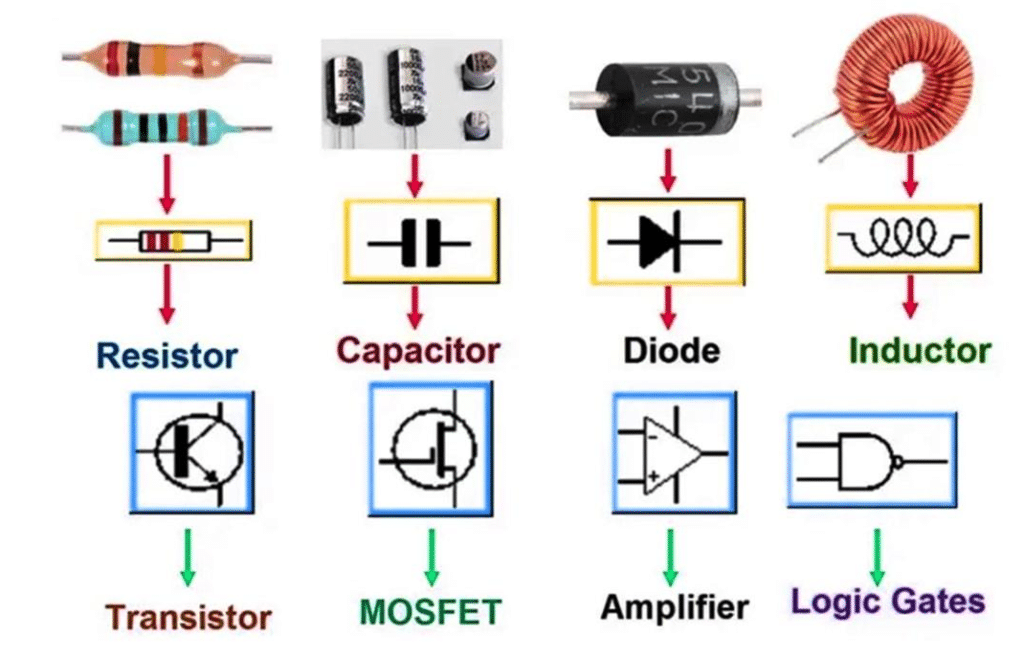


Resistor Circuits
Resistors are frequently used for:
- Current limiting
- Voltage division
- Biasing
- Feedback
- Signal termination
For two series resistors:
For parallel resistors:
A voltage divider can be expressed as:
Capacitor Circuits
Capacitors are widely used for:
- Filtering
- Coupling
- Decoupling
- Timing
- Energy storage
For a simple RC circuit, the time constant is:
A larger or produces a longer time constant.
Diode Circuits
A diode primarily permits current to flow more easily in one direction than the other.
Applications include:
- Rectification
- Reverse-polarity protection
- Signal clipping
- Voltage regulation
- Switching
Transistor Circuits
Transistors are central to modern electronics.
A transistor can operate in:
Cutoff region → switch OFF
Active region → amplification
Saturation region → switch ON
This makes transistor circuits useful in both analog and digital systems.
Operational Amplifier Circuits
An operational amplifier, or op-amp, is a high-gain differential amplifier used in numerous analog applications.
Common configurations include:
- Inverting amplifier
- Non-inverting amplifier
- Voltage follower
- Summing amplifier
- Integrator
- Differentiator
- Active filter
For an ideal inverting amplifier:
For a non-inverting amplifier:
These relationships allow engineers to establish predictable voltage gain.
Examples of Electronic Circuits 🧪
Example 1: LED Current-Limiting Circuit
Suppose a 5 V source drives an LED with an approximate forward voltage of 2 V and desired current of 15 mA.
The resistor voltage is:
Therefore:
A practical standard resistor close to this value can be selected, while checking LED current and resistor power.
Example 2: Transistor Switching
Consider a microcontroller controlling a small relay.
The microcontroller output should not necessarily drive the relay directly. A transistor can be used as an interface.
Basic structure:
A flyback diode is typically required across an inductive relay coil to suppress the voltage generated when current is interrupted.


Example 3: RC Low-Pass Filter
An RC low-pass filter allows low-frequency signals to pass while attenuating higher frequencies.
Its cutoff frequency is approximately:
If:
and
then:
This principle is widely useful for sensor conditioning and signal processing.
Diagrams and Engineering Tables 📊
A simplified electronic signal chain can be represented as:
        ┌──────────┐
Input ─►│ Amplifier│
        └────┬─────┘
             │
             ▼
        ┌──────────┐
        │  Filter  │
        └────┬─────┘
             │
             ▼
        ┌──────────┐
        │   ADC    │
        └────┬─────┘
             │
             ▼
        ┌──────────┐
        │Processor │
        └──────────┘
The design philosophy is modular: each circuit block performs a defined task.
| Parameter | Symbol | Unit |
|---|---|---|
| Voltage | (V) | Volt |
| Current | (I) | Ampere |
| Resistance | (R) | Ohm |
| Capacitance | (C) | Farad |
| Inductance | (L) | Henry |
| Power | (P) | Watt |
| Frequency | (f) | Hertz |
| Gain | (A_v) | Dimensionless |


Real-World Applications 🌍
Electronic circuits are everywhere.
Automotive Engineering
Modern vehicles contain circuits for:
- Engine control
- Battery management
- Sensors
- Lighting
- Infotainment
- Driver-assistance systems
- Motor control in electric vehicles
Industrial Automation
Industrial controllers use electronic circuits for:
- Sensor interfaces
- Motor drives
- PLC systems
- Safety systems
- Communication
- Process monitoring
Consumer Electronics
Smartphones, televisions, laptops, cameras, and gaming systems contain enormous numbers of integrated circuits combined with passive components and power-management circuits.
Renewable Energy
Solar and energy-storage systems rely on power electronics for:
and
conversion.
Medical Electronics
Electronic circuits are fundamental to:
- Patient monitors
- ECG equipment
- Imaging systems
- Infusion equipment
- Wearable sensors
Reliability and safety are especially important in these applications.
Common Mistakes ⚠️
Ignoring Component Power Ratings
Calculating resistance without calculating power can lead to overheated components.
Reversing Polarized Components
Electrolytic capacitors, diodes, LEDs, and some integrated devices have polarity requirements.
Incorrect connections can cause failure.
Poor Grounding
A circuit may appear mathematically correct but behave incorrectly because of:
- Ground loops
- Excessive impedance
- Poor PCB return paths
- Noise coupling
Using Ideal Models in Real Hardware
Real components have:
- Tolerances
- Parasitic capacitance
- Parasitic inductance
- Temperature dependence
- Leakage current
- Frequency limitations
An ideal simulation therefore does not guarantee perfect physical performance.
Forgetting Decoupling Capacitors
Digital ICs can generate rapid current changes. Local bypass or decoupling capacitors are commonly used to help maintain supply integrity.
Challenges and Solutions 🛠️
| Challenge | Likely Cause | Engineering Solution |
|---|---|---|
| Excessive heat | High power dissipation | Improve component rating/cooling |
| Signal noise | Poor grounding/layout | Improve grounding and filtering |
| Unstable amplifier | Feedback/layout issues | Analyze stability and compensation |
| Voltage drop | Excessive load/current | Increase supply capability |
| Circuit failure | Incorrect polarity | Verify schematic and datasheets |
| Oscillation | Unwanted feedback | Improve layout/compensation |
| Simulation mismatch | Non-ideal hardware | Include realistic models |
| EMI problems | Fast switching currents | Optimize PCB layout and filtering |
Case Study: Designing a Sensor Interface
Imagine an industrial temperature-monitoring system.
The sensor produces a small analog voltage, but the microcontroller’s ADC requires a clean signal within a specific voltage range.
A practical architecture could be:
Temperature Sensor→Signal Conditioning→Low–Pass Filter→ADC→Microcontroller
Stage 1: Sensor
The sensor converts temperature into an electrical signal.
Stage 2: Amplification
If the sensor signal is only a few hundred millivolts, an op-amp circuit can increase its amplitude.
Stage 3: Filtering
Electrical noise can be reduced with an appropriate low-pass filter.
Stage 4: ADC Interface
The conditioned analog signal is converted into digital information.
Stage 5: Processing
The microcontroller converts the ADC result into engineering units such as °C.
Stage 6: Communication
The processed data can be transmitted to a PLC, computer, cloud platform, or industrial monitoring system.
This example demonstrates an important engineering principle: a successful electronic product is usually a collection of carefully coordinated circuit blocks rather than one isolated circuit.
Essential Tips for Electronic Circuit Design 💡
- Start with specifications, not components.
- Draw the schematic before building the hardware.
- Calculate voltage, current, and power for critical components.
- Use datasheets rather than relying only on nominal component values.
- Simulate complicated circuits before manufacturing.
- Leave safety margins in component ratings.
- Consider temperature effects.
- Keep analog and noisy digital sections appropriately separated.
- Use proper grounding and power distribution.
- Measure signals with an oscilloscope when a multimeter is insufficient.
- Document every design revision.
- Prototype before committing to expensive PCB production.
For students, the best learning strategy is to connect equations with physical measurements. Calculate a voltage, build the circuit, measure it, and then explain why the measured value differs from the ideal prediction.
That cycle develops genuine engineering intuition. 🔬
FAQs
What is the difference between an electrical and electronic circuit?
Electrical circuits often focus on power transmission and energy conversion, while electronic circuits generally emphasize controlling, processing, amplifying, or switching electrical signals. The boundary is not absolute, and many modern systems contain both.
Why are resistors important in electronic circuits?
Resistors can limit current, divide voltage, establish transistor bias conditions, provide feedback, terminate signals, and control circuit operating points.
What does a transistor do?
A transistor can function as an amplifier or a switch. Its ability to control a larger current or voltage using a smaller control signal makes it one of the fundamental devices in electronics.
Why are capacitors used in power supplies?
Capacitors can reduce voltage fluctuations, store energy temporarily, filter unwanted AC components, and provide local transient current.
What is circuit simulation?
Circuit simulation is the computational analysis of an electronic circuit before or alongside physical prototyping. It can help engineers investigate voltages, currents, frequency response, switching behavior, and transient conditions.
Why is PCB layout important?
PCB layout affects electrical performance, thermal behavior, electromagnetic compatibility, manufacturability, and reliability. A correct schematic can still produce a poor physical circuit if the layout is badly designed.
Should beginners learn analog or digital electronics first?
A basic understanding of voltage, current, resistance, capacitance, diodes, and transistors provides a useful foundation for both. Beginners can then progress toward analog, digital, embedded, or power electronics depending on their goals.
Is electronic circuit theory useful for professional engineers?
Absolutely. Even engineers working with microcontrollers, embedded systems, robotics, automation, or software-controlled hardware benefit from understanding circuit behavior. Modern engineering increasingly requires interaction between hardware and software.
Conclusion 🚀
Electronic circuits form the technological foundation beneath modern engineering. Their operation begins with fundamental relationships such as (V=IR) and Kirchhoff’s laws, but practical design requires much more than mathematical calculation.
Engineers must understand components, circuit topology, signal behavior, power dissipation, simulation, PCB layout, testing, troubleshooting, and real-world limitations.
The progression from a simple resistor network to an amplifier, regulated power supply, sensor interface, or embedded system demonstrates how fundamental electronic principles scale into sophisticated engineering products.
Electronic Circuits: Fundamentals and Applications, 3rd Edition is particularly relevant to this learning path because it combines foundational electronic knowledge with practical areas such as circuit construction, fault finding, simulation, CAD, amplifiers, logic circuits, power supplies, oscillators, and microcontrollers.
For students, the key is to learn by combining theory + calculation + simulation + measurement + troubleshooting. For professional engineers, the same principles provide the foundation for reliable design decisions.
Ultimately, electronics engineering is about turning controlled electrical behavior into useful technology. ⚡🔧
From a single resistor to a complete embedded system, the same fundamental principles remain at the heart of the design.