Practical Arduino Engineering: End-to-End Development with Arduino, Fusion 360, 3D Printing, and Eagle
Introduction
Arduino engineering becomes far more powerful when programming, electronics, mechanical design, PCB development, and physical manufacturing are treated as one connected workflow. Instead of building a prototype on a breadboard and stopping there, engineers can transform an idea into a complete physical product using Arduino, Fusion 360, Eagle, and 3D printing. ⚙️🔌🖨️
This end-to-end approach is especially useful for students, makers, engineering professionals, researchers, and product developers who want to understand how an electronic concept becomes a working device.


An Arduino-based system can begin with a simple question: What should the device do? From there, the engineer selects sensors and actuators, develops firmware, creates the electronic circuit, designs an enclosure, produces a PCB, manufactures mechanical components, assembles everything, and performs testing.


The most valuable lesson is that successful engineering is rarely about one component. It is about integration. 🔧
Background Theory
From Prototype to Product
Arduino is widely associated with beginner electronics, but the underlying engineering concepts extend far beyond introductory projects.
A typical development process can contain several layers:
Concept → Circuit → Firmware → PCB → Mechanical Design → Manufacturing → Assembly → Testing
Each stage influences the others.
For example, choosing a particular sensor may affect:
- PCB dimensions
- Connector placement
- Enclosure geometry
- Power requirements
- Firmware architecture
- Cooling requirements
- Cable routing
- Manufacturing cost
This is why an end-to-end engineering workflow is more valuable than treating electronics and mechanical design as isolated disciplines.
The Role of Each Tool
Arduino provides the programmable control platform.
Fusion 360 can be used to develop mechanical components, enclosures, brackets, mounting systems, and assemblies.
Eagle is associated with electronic schematic and PCB design workflows.
3D printing provides a rapid method for manufacturing physical prototypes.
Together, these tools create a bridge between digital engineering and physical hardware. 🌐➡️🔩
Definition
What Is Practical Arduino Engineering?
Practical Arduino engineering is the systematic development of physical electronic systems using programmable micro-controllers together with circuit design, mechanical modeling, fabrication, and testing techniques.
It differs from a simple Arduino tutorial because the goal is not merely to make an LED blink or read a sensor.
The objective is to create a system that can be:
- Designed
- Tested
- Reproduced
- Manufactured
- Maintained
- Improved
- Integrated into a real environment
What Is an End-to-End Workflow?
An end-to-end workflow means following the project from the original engineering requirement through to a functional physical prototype.
For example:
Idea 💡 → Arduino Prototype 🔌 → Schematic 📐 → PCB 🟩 → Fusion 360 Enclosure 🧩 → 3D Print 🖨️ → Assembly 🔧 → Testing ✅
This approach encourages engineers to consider practical constraints early rather than discovering them at the end.
Step-by-Step Arduino Engineering Workflow
Step 1: Define the Engineering Requirement
Start by describing what the device must accomplish.
Instead of saying:
“I want to build an Arduino project.”
define the actual requirement:
“I need a device that monitors environmental conditions and displays warnings when conditions become abnormal.”
This immediately provides direction.
Consider:
- Inputs
- Outputs
- Power source
- Operating environment
- Physical dimensions
- User interaction
- Communication requirements
- Safety considerations
- Expected lifetime
Step 2: Select the Hardware
Choose an Arduino-compatible controller based on the application rather than popularity.
Consider:
- Number of digital inputs
- Analog inputs
- Communication interfaces
- Memory
- Processing requirements
- Voltage compatibility
- Physical size
- Power consumption
Then select appropriate sensors, displays, motors, relays, LEDs, buttons, and communication modules.
Step 3: Build the Initial Prototype
A breadboard is useful because components can be connected and modified quickly.
At this stage, focus on functionality rather than appearance.
🔌 Prototype objective: prove that the concept works.
Do not spend hours designing a beautiful enclosure before confirming that the electronics behave correctly.
Step 4: Develop the Firmware
The Arduino program should be structured around clearly defined functions.
A professional project might separate:
- Sensor acquisition
- Data processing
- User interface
- Communication
- Fault handling
- Output control
Avoid writing the entire application as one large block of code.
Good organization makes troubleshooting significantly easier.
Step 5: Create the Schematic
Once the prototype works, document the electronic design.
The schematic should clearly represent:
- Components
- Power connections
- Signal paths
- Connectors
- Protection components
- Communication interfaces
This schematic becomes the foundation for PCB development.
Step 6: Design the PCB
Move from temporary wiring to a dedicated printed circuit board.


PCB development involves:
- Creating the schematic
- Assigning footprints
- Arranging components
- Routing traces
- Reviewing clearances
- Adding labels
- Checking manufacturing requirements
- Performing design-rule checks
Component placement is not merely an aesthetic decision. It can influence signal integrity, heat management, assembly, and enclosure dimensions.
Step 7: Design the Mechanical Structure
The electronics now need a physical home.
Fusion 360 can be used to create:
- Enclosures
- Brackets
- Covers
- Mounting plates
- Sensor holders
- Cable-management features
- Mechanical interfaces


The PCB should be considered during mechanical design.
Mounting holes, connectors, buttons, displays, ventilation, and cable access should all be positioned intentionally.
Step 8: Produce the Prototype
3D printing allows engineers to create a physical enclosure quickly.
A prototype can reveal problems that are difficult to detect on a computer screen.
For example:
- A connector may be inaccessible.
- A cable may interfere with the enclosure.
- A screw may be too close to another component.
- A display may be difficult to see.
- The PCB may not fit as expected.
Step 9: Assemble and Test
After mechanical and electronic integration, assemble the complete device.
Testing should include:
Electrical testing → Functional testing → Mechanical testing → Environmental testing → User testing
Document failures instead of simply fixing them.
A failure is engineering information. 🧪
Comparison
Breadboard vs Custom PCB
| Feature | Breadboard | Custom PCB |
|---|---|---|
| Modification | Very easy | More difficult |
| Prototype speed | Very high | Moderate |
| Reliability | Limited | Higher |
| Appearance | Temporary | Professional |
| Manufacturing | Not suitable for final products | Suitable |
| Wiring | External jumpers | Integrated traces |
| Repeatability | Lower | Higher |
3D Printing vs Traditional Manufacturing
| Feature | 3D Printing | Traditional Manufacturing |
|---|---|---|
| Prototype speed | Excellent | Moderate |
| Complex shapes | Excellent | Depends on process |
| Small quantities | Cost-effective | Often expensive |
| Surface finish | Variable | Often superior |
| Mass production | Usually less suitable | Often preferred |
| Design changes | Easy | Can be expensive |
Arduino Prototype vs Engineered Product
A prototype asks:
“Does the concept work?”
An engineered product asks:
“Does the concept work reliably, safely, repeatedly, and economically?”
That difference represents the transition from hobby experimentation to engineering practice.
Diagrams and Engineering Tables
End-to-End Development Diagram
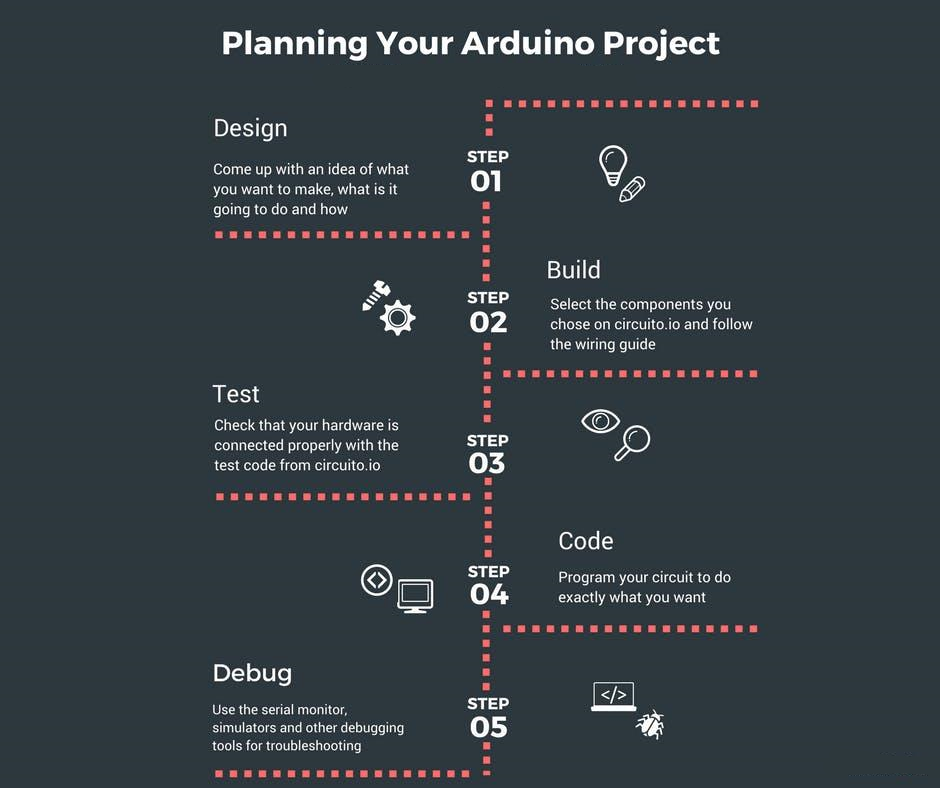


A practical workflow can be represented as:
Requirement
↓
Arduino Prototype
↓
Firmware Development
↓
Schematic
↓
PCB Layout
↓
Fusion 360 Mechanical Design
↓
3D Printing
↓
Assembly
↓
Testing
↓
Revision
↓
Final Prototype
Design Review Checklist
| Area | Important Question |
|---|---|
| Electronics | Are all components compatible? |
| Power | Is the supply appropriate? |
| Firmware | What happens when a sensor fails? |
| PCB | Are traces and components correctly placed? |
| Mechanical | Does everything physically fit? |
| Thermal | Can heat escape where necessary? |
| Manufacturing | Can the design actually be produced? |
| Maintenance | Can components be accessed? |
| Safety | Are foreseeable hazards controlled? |
Practical Examples
Example 1: Smart Plant Monitoring Device 🌱
An Arduino can monitor soil conditions and environmental parameters.
The initial prototype might use sensors connected directly to an Arduino board.
Once the system is validated, the engineer can create a custom PCB, design a compact Fusion 360 enclosure, and 3D-print a housing suitable for indoor use.
The final device can include:
- Sensor interfaces
- Status LEDs
- User controls
- Wireless communication
- Battery or external power
- Protective enclosure
Example 2: Desktop Automation Controller
Imagine a small controller designed to operate a motorized mechanism.
The development process could begin with:
Arduino + motor driver + switches + prototype mechanism
After testing, the engineer can replace temporary wiring with a custom PCB and design a mechanical mounting system around the motor, controller, and connectors.
Example 3: Educational Robotics Platform 🤖
Students can create a robotic platform using Arduino for control, Fusion 360 for structural components, and 3D printing for wheels, brackets, sensor mounts, and protective covers.
This creates a complete engineering learning experience instead of focusing exclusively on programming.
Real-World Applications
Industrial Automation
Arduino-compatible controllers can be useful for prototyping:
- Monitoring systems
- Control interfaces
- Sensor networks
- Test equipment
- Machine prototypes
Industrial deployments may require more specialized controllers depending on safety, reliability, certification, and environmental requirements.
Robotics
Robotics is naturally suited to an integrated workflow.
A robot may require:
Sensors + Controller + Motors + Power Electronics + Mechanical Structure + Firmware
Fusion 360 can help develop the mechanical structure while Arduino manages control logic during prototyping.
IoT Devices
Arduino platforms can be integrated with communication technologies to create connected devices.
Applications include:
- Environmental monitoring
- Smart agriculture
- Building monitoring
- Equipment tracking
- Educational IoT systems
Engineering Education
The workflow is particularly valuable in universities and technical education because students can experience multiple engineering disciplines within one project.
They learn that a successful product requires cooperation between:
Electrical Engineering ⚡ + Software Engineering 💻 + Mechanical Engineering ⚙️ + Manufacturing 🏭
Common Mistakes
Designing the Enclosure Too Early
A common mistake is designing the enclosure before the electronics have stabilized.
The PCB, connectors, cables, and components may change repeatedly.
Better approach: stabilize the functional architecture before finalizing the mechanical design.
Ignoring Power Requirements
Beginners often focus on the Arduino board while overlooking motors, displays, wireless modules, and sensors.
A system can appear to work during testing and later become unstable because the power architecture is inadequate.
Poor Connector Placement
A PCB may work perfectly while still being difficult to assemble.
Connectors should be positioned with accessibility and cable routing in mind.
Insufficient Testing
A prototype working once does not demonstrate reliability.
Test repeated startup, sensor failures, communication interruptions, mechanical movement, and unexpected user actions.
Overcomplicating the First Prototype
The first prototype should answer the most important engineering question.
Do not build every feature simultaneously.
Build → test → learn → improve. 🔄
Challenges & Solutions
Challenge: Limited Physical Space
Solution: use CAD early enough to understand the relationship between PCB dimensions and enclosure geometry.
Challenge: Electrical Noise
Motors, switching circuits, and communication hardware can introduce unwanted interference.
Solution: improve grounding, power distribution, PCB layout, filtering, wiring, and physical separation where appropriate.
Challenge: Mechanical Misalignment
A PCB mounting hole or connector may not line up with the enclosure.
Solution: use the PCB dimensions and mounting information as references within the CAD model.
Challenge: Difficult Maintenance
A beautifully enclosed product can become frustrating if components cannot be reached.
Solution: design removable covers, accessible connectors, and service-friendly fasteners.
Challenge: Prototype Failure
Not every prototype will work.
Solution: treat each iteration as a controlled engineering experiment. Record what failed, why it failed, and what changed in the next version.
Case Study
Development of a Compact Environmental Monitor
Consider a hypothetical engineering team developing a compact environmental monitoring device.
The team begins with an Arduino-compatible controller and several sensors.
The first prototype is assembled using temporary connections.
The firmware successfully reads sensor information and activates warning indicators.
The next stage is PCB development.
The engineers create a schematic and organize the components on a custom board. They then design a compact enclosure in Fusion 360.
During the first physical fitting, they discover that the USB connector is difficult to access.
Rather than modifying the electronics immediately, they update the enclosure geometry.
A second 3D-printed enclosure provides better access.
During extended testing, the team notices that the enclosure traps excessive heat around one component. They introduce ventilation features and revise the mechanical design.
The result is not simply an Arduino project.
It is an engineering development cycle:
Prototype → Test → Failure → Analysis → Modification → New Prototype → Validation
This iterative process is fundamental to practical engineering.
Essential Tips
Start With Requirements 🎯
Write down what the device must do before selecting components.
Keep Documentation Updated
Maintain:
- Schematics
- Firmware versions
- PCB revisions
- CAD files
- Component lists
- Test results
Design for Assembly
Ask how the device will actually be put together.
A design that is easy to manufacture is usually better than one that is merely attractive.
Use Version Control
Keep identifiable versions of software and hardware.
For example:
Prototype A → PCB Rev A → PCB Rev B → Final Prototype
This makes troubleshooting much easier.
Design for Failure
Ask:
“What happens if this sensor disconnects?”
“What happens if power is interrupted?”
“What happens if communication stops?”
Robust engineering considers abnormal conditions, not just normal operation.
Test Before Scaling
Do not assume that a successful prototype automatically becomes a production-ready device.
Production may introduce new requirements involving:
- Certification
- Reliability
- Component availability
- Manufacturing tolerances
- Supply chains
- Safety
- Cost
FAQs
What is Arduino engineering?
Arduino engineering involves using Arduino-compatible micro-controllers as part of a broader engineering workflow that can include electronics, programming, PCB design, mechanical CAD, manufacturing, and testing.
Why combine Arduino with Fusion 360?
Arduino handles the electronic control side, while Fusion 360 can be used to design physical structures such as enclosures, brackets, mounts, and mechanical assemblies.
What is the purpose of Eagle in an Arduino project?
Eagle can be used for electronic schematic and PCB design, allowing engineers to transition from temporary prototype wiring to a custom circuit board.
Is 3D printing necessary for Arduino projects?
No. However, 3D printing is extremely useful when a project requires custom enclosures, brackets, sensor mounts, or other physical components.
Can beginners learn this complete workflow?
Yes. Beginners can start with a simple Arduino circuit and gradually introduce CAD, PCB design, and fabrication.
Should I create a PCB immediately?
Usually, it is better to validate the core concept first. Once the circuit and firmware are sufficiently stable, moving toward a PCB can improve reliability and repeatability.
Is an Arduino prototype production-ready?
Not automatically. A prototype demonstrates functionality, while a production design must also address reliability, safety, manufacturability, testing, component availability, and applicable regulations.
What is the most important engineering skill in an Arduino project?
Systems thinking. Understanding how electronics, software, mechanical design, manufacturing, and testing interact is often more valuable than mastering one tool in isolation.
Conclusion
Practical Arduino engineering is about much more than connecting a sensor to a development board. 🚀
The real engineering opportunity appears when the project moves through the complete development chain:
Idea → Prototype → Firmware → Circuit → PCB → CAD → 3D Printing → Assembly → Testing → Refinement
Arduino provides an accessible platform for experimentation. PCB design transforms temporary wiring into a structured electronic system. Fusion 360 connects electronics with mechanical engineering, while 3D printing makes physical iteration fast and affordable.
The most important principle is iteration.
A strong engineer does not expect the first prototype to be perfect. Instead, each prototype provides information that improves the next version.
Whether you are a university student developing your first robotic system, a professional prototyping an IoT product, or an engineer exploring rapid hardware development, this integrated workflow provides a practical bridge between digital concepts and real-world machines. ⚙️💡🔌
The ultimate goal is not simply to make an Arduino project work—it is to understand why it works, how to improve it, how to manufacture it, and how to make it reliable in the real world.