Electronic Troubleshooting 4th Edition: A Complete Practical Guide to Diagnosing Electronic Circuits and Devices
Introduction
Electronic troubleshooting is the systematic process of finding, identifying, and correcting faults in electronic circuits, components, and systems. From a simple LED circuit to an industrial motor controller, the fundamental objective is the same: determine why the circuit is not behaving as expected and restore it to proper operation. 🔧⚡
For engineering students, technicians, hobbyists, and professional engineers, troubleshooting is one of the most valuable practical skills in electronics. Knowing Ohm’s law or Kirchhoff’s laws is important, but being able to apply those principles to a faulty circuit is what turns theoretical knowledge into engineering capability.
A good troubleshooter does not randomly replace components. Instead, they collect evidence, measure electrical quantities, compare actual values with expected values, isolate the faulty section, and verify the repair.
Modern electronic systems can contain thousands or even millions of components. Nevertheless, many failures can be reduced to a small number of fundamental problems:
- ⚡ Incorrect voltage
- 🔌 Open circuits
- 🔥 Short circuits
- 🌡️ Excessive temperature
- 🧩 Failed components
- 📉 Poor connections
- 📡 Unexpected signals
- 💧 Environmental damage
- 💻 Software or control faults
The key is to approach the problem logically rather than experimentally.


Background Theory
Why Electronic Troubleshooting Requires Engineering Analysis
An electronic circuit operates according to predictable electrical relationships. When a circuit fails, at least one part of the expected behavior has changed.
For a resistive circuit, Ohm’s law provides the fundamental relationship:
V = I × R
where:
- V = voltage in volts (V)
- I = current in amperes (A)
- R = resistance in ohms (Ω)
If a 1 kΩ resistor is connected to a 10 V supply, the theoretical current is:
I = V/R = 10/1000 = 10 mA
If the measured current is approximately zero, an open circuit may exist. If the current is extremely high, a short circuit or incorrectly connected component may be present.
Kirchhoff’s Laws
Troubleshooting becomes more powerful when Kirchhoff’s laws are applied.
Kirchhoff’s Current Law states:
ΣI_in = ΣI_out
At a circuit node, the total current entering must equal the total current leaving.
Kirchhoff’s Voltage Law states:
ΣV = 0
around a closed electrical loop.
These relationships allow engineers to predict what measurements should look like before touching a test instrument.
Signal-Based Troubleshooting
In digital and analog systems, troubleshooting is not limited to DC voltage.
Engineers may need to examine:
- Voltage levels
- Current
- Resistance
- Frequency
- Phase
- Waveform shape
- Noise
- Ripple
- Timing
- Duty cycle
- Logic states
An oscilloscope, for example, can reveal a distorted waveform that a standard multimeter cannot detect.
Definition
What Is Electronic Troubleshooting?
Electronic troubleshooting is the structured process of detecting, isolating, diagnosing, repairing, and verifying faults in electronic equipment or circuits.
The process can be represented as:
Symptom → Measurement → Hypothesis → Isolation → Repair → Verification
A professional troubleshooting procedure should answer six questions:
- What is the expected behavior?
- What is the actual behavior?
- Where does the expected behavior first disappear?
- What component or condition can explain the difference?
- What corrective action is required?
- Does the repaired system now meet its specifications?
Fault Categories
Open Circuit
An open circuit interrupts current flow.
Typical causes include:
- Broken wires
- Cracked solder joints
- Burned PCB traces
- Failed switches
- Broken component leads
Short Circuit
A short circuit creates an unintended low-resistance path.
It may cause:
I ↑ → P ↑ → Temperature ↑ → Component failure
because electrical power can be calculated as:
P = V × I
or
P = I²R
Component Failure
Electronic components can fail in several ways.
A resistor may become open or change value. A capacitor may leak, short, or lose capacitance. A semiconductor may develop an internal short or open circuit.
Intermittent Fault
Intermittent failures are particularly difficult because the circuit may operate correctly during testing.
Causes include:
- Vibration
- Thermal expansion
- Loose connectors
- Cracked solder
- Oxidation
- Mechanical stress
Step-by-Step Electronic Troubleshooting
Step 1: Define the Symptom
Never begin by replacing components.
First document exactly what is wrong.
For example:
“The power LED illuminates, but the motor does not rotate.”
This is much more useful than saying:
“The circuit is broken.”
Step 2: Check Safety Conditions
Before measurements, determine whether the circuit contains hazardous voltages, stored energy, high currents, rotating machinery, or hot components.
⚠️ Never assume that a switched-off device is electrically safe.
Large capacitors can retain energy after power is removed.
Step 3: Perform a Visual Inspection
Look for:
- Burn marks
- Swollen capacitors
- Broken connectors
- Discolored components
- Corrosion
- Cracked PCB traces
- Loose wires
- Missing components
- Solder bridges
Visual inspection can sometimes identify the failure before electrical testing begins.


Step 4: Verify the Power Supply
Power problems are among the most common causes of electronic failure.
Measure:
V_supply
Then compare it with the expected specification.
For example, if a circuit requires 12 V but the measured voltage is 7.4 V, investigating individual ICs before checking the power supply would be inefficient.
Step 5: Divide the Circuit into Functional Blocks
Complex circuits should be divided into sections.
A simplified signal path might be:
Power → Input → Amplifier → Controller → Driver → Output
Instead of testing 100 components individually, determine which block is failing.
Step 6: Measure Critical Test Points
Create a table:
| Test Point | Expected | Measured | Result |
|---|---|---|---|
| TP1 Supply | 12 V | 12.1 V | ✓ |
| TP2 Regulator | 5 V | 5.02 V | ✓ |
| TP3 Sensor | 2.5 V | 0 V | ✗ |
| TP4 Controller | 3.3 V | 3.3 V | ✓ |
The first abnormal point can provide a major clue.
Step 7: Isolate the Fault
Once the faulty block is identified, narrow the investigation.
For example:
Sensor → Signal Conditioning → Microcontroller
If the sensor output is correct but the signal-conditioning output is zero, attention should shift to the signal-conditioning stage.
Step 8: Test Individual Components
Depending on the component, use:
- Multimeter
- LCR meter
- Oscilloscope
- Logic analyzer
- Transistor tester
- Power supply
- Function generator
- Thermal camera
Step 9: Repair the Fault
Repair may involve:
- Replacing a component
- Resoldering a connection
- Repairing a PCB trace
- Replacing a connector
- Correcting wiring
- Removing contamination
- Updating firmware
Step 10: Verify the Repair
A repair is incomplete until the system has been tested under normal operating conditions.
Measure the same parameters that originally revealed the fault.
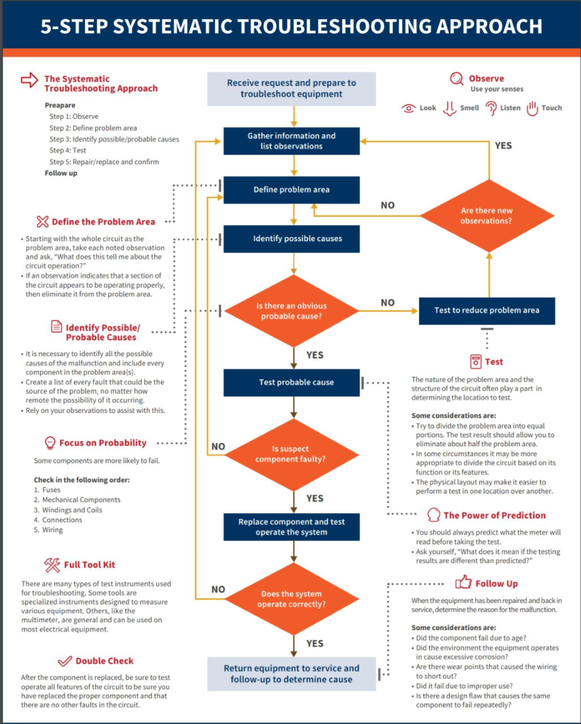


Comparison of Troubleshooting Methods
Different troubleshooting strategies are useful in different situations.
| Method | Principle | Best Application |
|---|---|---|
| Half-split | Divide circuit into sections | Complex signal paths |
| Signal tracing | Follow signal from input to output | Amplifiers and communication circuits |
| Voltage comparison | Compare test points | Power and control circuits |
| Resistance testing | Identify abnormal resistance | Unpowered circuits |
| Substitution | Replace suspected component | Confirmed component-level faults |
| Thermal inspection | Find abnormal heat | Power electronics |
| Oscilloscope analysis | Examine waveforms | Analog and digital systems |
Half-Split Method
The half-split method is especially efficient for large systems.
Suppose a signal passes through eight stages.
Instead of testing:
1 → 2 → 3 → 4 → 5 → 6 → 7 → 8
test around the middle:
1 → 2 → 3 → 4 | 5 → 6 → 7 → 8
If the signal is correct at stage 4 but missing at stage 5, half of the remaining circuit can immediately be eliminated.
This dramatically reduces troubleshooting time. ⏱️
Diagrams and Troubleshooting Tables
Basic Fault-Diagnosis Flow


A practical troubleshooting sequence is:
Symptom
↓
Visual Inspection
↓
Power Verification
↓
Functional Block Analysis
↓
Test Measurements
↓
Fault Isolation
↓
Component Testing
↓
Repair
↓
Functional Verification
Measurement Reference Table
| Measurement | Possible Fault Indication |
|---|---|
| 0 V instead of expected voltage | Open circuit, missing supply, short, failed regulator |
| Excessive current | Short circuit or overloaded component |
| High resistance | Open connection or damaged component |
| Low resistance | Short circuit or parallel path |
| Correct DC voltage but incorrect waveform | Oscillation, noise, switching, timing, or signal fault |
| Intermittent voltage | Loose connection or intermittent component |
| Excessive temperature | Overcurrent, overload, poor cooling, failed semiconductor |
Examples
Example 1: LED Does Not Illuminate
Consider a simple circuit containing:
5 V supply → resistor → LED → ground
If the LED does not illuminate, possible causes include:
- Reversed LED
- Open resistor
- Broken wire
- Failed LED
- Missing supply voltage
- Poor solder joint
Start with the supply voltage.
Then measure voltage across the LED.
If the supply is 5 V but the LED has approximately 0 V across it, investigate the current path and polarity.
Example 2: DC Motor Does Not Start
Suppose a 12 V motor controller is operating but the motor remains stationary.
Check:
- Supply voltage
- Controller output
- Enable signal
- Motor connector
- Motor winding resistance
- Mechanical load
If the controller output is 12 V but the motor receives 0 V, the connector or wiring is likely responsible.
Example 3: Microcontroller System Resets Randomly
Possible causes include:
- Insufficient power supply
- Voltage ripple
- Electromagnetic interference
- Watchdog reset
- Firmware fault
- Poor grounding
- Inadequate decoupling capacitors
An oscilloscope is particularly useful because a multimeter may show a stable average voltage while missing short voltage dips.
Real-World Applications
Electronic troubleshooting is used across almost every engineering discipline.
Automotive Electronics
Technicians diagnose:
- ECU faults
- Sensor failures
- Ignition systems
- Battery-management systems
- Lighting controllers
- CAN communication problems
Industrial Automation
Engineers troubleshoot:
- PLC systems
- Motor drives
- Variable-frequency drives
- Sensors
- Actuators
- Industrial communication networks
Consumer Electronics
Troubleshooting is essential for:
- Televisions
- Computers
- Power supplies
- Audio equipment
- Smart devices
- Battery-powered products
Aerospace and Defense Electronics
Highly reliable troubleshooting procedures are used for:
- Navigation systems
- Communication equipment
- Flight-control electronics
- Power distribution
- Instrumentation
In these applications, troubleshooting must be systematic because random component replacement can introduce additional failures.
Common Mistakes
Replacing Components Without Testing
This is one of the most common beginner mistakes.
A failed transistor may actually be a consequence of a faulty power supply.
Measuring Resistance on a Powered Circuit
Resistance measurements should normally be performed with power removed.
Attempting resistance measurement on a live circuit can produce incorrect readings and may damage the meter.
Ignoring Ground Connections
Many apparent signal failures are actually grounding problems.
Always verify:
Ground continuity + reference voltage + signal voltage
Using the Wrong Meter Range
Incorrect instrument settings can cause inaccurate readings or equipment damage.
Testing Only When the Circuit Works
Intermittent faults require observation during the failure.
A thermal camera, oscilloscope, vibration test, or controlled temperature change can sometimes reproduce the fault.
Challenges and Solutions
| Challenge | Solution |
|---|---|
| Intermittent fault | Monitor signals continuously |
| Complex PCB | Divide into functional blocks |
| No schematic | Reverse-trace important sections carefully |
| Multiple failures | Fix power and safety-critical faults first |
| Difficult access | Use suitable test points |
| Thermal failure | Test at different temperatures |
| Electromagnetic interference | Inspect grounding, shielding, and cable routing |
| Hidden PCB damage | Use continuity and visual inspection |
The “Fault Tree” Approach
When multiple causes are possible, create a logical tree.
For example:
Motor Not Running
→ Is supply present?
→ Is controller enabled?
⚡ → Is output voltage present?
→ Is motor connected?
→ Is motor winding continuous?
Each answer eliminates possibilities.
Case Study: Troubleshooting a 12 V Motor Control Board
Imagine an industrial control board designed to drive a 12 V DC motor.
The reported symptom is:
“The controller powers up, but the motor does not rotate.”
Initial Inspection
The power LED is illuminated. No obvious burned components are visible.
Power Measurement
Measured supply:
V_in = 12.1 V
This is acceptable.
Controller Output
The enable signal is present.
However, the motor output measures:
V_motor = 0.2 V
This is abnormal.
Functional Isolation
The controller receives the correct input command, so the investigation moves toward the output driver.
Testing reveals that the MOSFET controlling the motor is shorted internally.
Root Cause
Further inspection shows insufficient heat dissipation around the MOSFET.
The component had experienced repeated thermal stress.
Corrective Action
The engineer:
- Replaced the MOSFET.
- Inspected the gate-drive circuit.
- Checked the PCB for thermal damage.
- Improved heat transfer.
- Tested motor current.
- Operated the system under full load.
The final test confirmed normal operation.
Important engineering lesson: replacing the failed MOSFET alone may restore operation temporarily, but identifying the reason for its failure prevents recurrence.
Essential Tips for Better Troubleshooting
Build a Measurement Baseline
Before declaring a component faulty, determine what a healthy circuit should measure.
Start With the Simplest Explanation
Check:
Power → Connections → Configuration → Signals → Components
before assuming an obscure internal failure.
Change One Variable at a Time
If you simultaneously replace three components and modify the wiring, you may never discover the actual cause.
Record Your Measurements
A troubleshooting log should include:
- Test point
- Expected value
- Actual value
- Instrument
- Circuit condition
- Date/time
- Result
Use the Right Instrument
A multimeter is excellent for voltage, current, resistance, and continuity, but it cannot replace an oscilloscope when waveform information is required.
Think in Terms of Evidence
Good troubleshooting is essentially an engineering investigation:
Observation → Measurement → Hypothesis → Test → Evidence → Conclusion
🧠 The goal is not to guess correctly. The goal is to prove what is wrong.
FAQs
What is the first step in electronic troubleshooting?
The first step is to clearly define the symptom and understand the expected behavior. Then perform a safety check and visual inspection before detailed electrical measurements.
Which tool is most important for electronic troubleshooting?
A digital multimeter is usually the fundamental starting tool. More advanced systems may require an oscilloscope, LCR meter, logic analyzer, thermal camera, or specialized diagnostic equipment.
Can I troubleshoot electronics without a circuit schematic?
Yes, but a schematic significantly improves efficiency. Without one, you can use PCB tracing, continuity measurements, component identification, and functional-block analysis to reconstruct the relevant circuit.
Why does an electronic circuit work intermittently?
Intermittent failures can result from cracked solder joints, loose connectors, thermal expansion, vibration, corrosion, electromagnetic interference, or components that fail only under specific operating conditions.
What is the difference between troubleshooting and testing?
Testing determines whether a component or system meets a specified requirement. Troubleshooting investigates why a system does not meet that requirement and identifies the root cause.
Should components always be removed before testing them?
Not necessarily. Some components can be tested in-circuit, but surrounding components may affect measurements. When an in-circuit measurement is ambiguous, removing or isolating the component can provide a more reliable result.
Why is voltage measurement often useful for troubleshooting?
Voltage measurements can quickly reveal where the expected electrical behavior disappears. Comparing several test points can help isolate a faulty circuit section without immediately removing components.
What is the most important troubleshooting skill?
The most important skill is logical fault isolation. Experienced engineers do not simply test everything; they choose measurements that eliminate the largest number of possible causes.
Conclusion
Electronic troubleshooting combines electrical theory, measurement techniques, practical experience, and logical reasoning. Whether diagnosing a simple LED circuit, a microcontroller board, an industrial motor controller, or a sophisticated embedded system, the fundamental process remains remarkably consistent.
The most effective approach is to:
Define the symptom → inspect the system → verify power → divide the circuit → measure test points → isolate the fault → repair the cause → verify operation.
⚡ The best troubleshooters are not necessarily those who memorize the largest number of component specifications. They are the engineers who can transform an uncertain failure into a sequence of measurable questions.
For students, troubleshooting provides a bridge between textbook equations and real hardware. For professionals, it provides a disciplined method for reducing downtime, preventing repeated failures, and improving system reliability.
Ultimately, every faulty circuit contains clues. The engineer’s job is to measure those clues, interpret them correctly, and turn them into a solution. 🔧📐⚡