Design of Steel Structures: Eurocode 3 – EN 1993-1-1 General Rules and Rules for Buildings
Steel structures are among the most efficient structural systems used in modern construction. From industrial halls and warehouses to office buildings, bridges, towers, and large-span roofs, steel provides an attractive combination of strength, ductility, speed of construction, and architectural flexibility. 🏗️⚙️
For engineers working in Europe and many countries influenced by European structural standards, Eurocode 3 (EN 1993) provides the principal framework for designing steel structures. Part 1-1, EN 1993-1-1: Eurocode 3 – Design of steel structures – Part 1-1: General rules and rules for buildings, establishes fundamental design principles and additional provisions for steel buildings.


This article presents the subject from both a beginner’s and professional engineer’s perspective, focusing on the engineering concepts behind the standard rather than reproducing copyrighted code provisions.
Background Theory
Steel design begins with a simple engineering question:
Can the structure safely carry the actions imposed on it throughout its intended service life?
The answer requires much more than checking whether a steel section is strong enough.
A structural engineer must consider:
- Permanent and variable actions
- Wind and snow
- Imposed loads
- Structural geometry
- Steel grade
- Cross-section behavior
- Member stability
- Connections
- Serviceability
- Durability
- Fabrication and erection
- Accidental and fire situations where applicable 🔥
Eurocode 3 works within the broader Eurocode system. EN 1990 establishes the basis of structural design, while EN 1991 provides rules for actions on structures. Eurocode 3 then addresses steel resistance, stability, serviceability, durability, and related design requirements.
The Eurocode design philosophy
A useful way to understand Eurocode design is through two major limit-state categories:
Ultimate Limit States (ULS)
These concern structural safety and include failure modes such as yielding, buckling, instability, rupture, and loss of equilibrium.
Serviceability Limit States (SLS)
These concern how the structure performs during normal use, including excessive deflection, vibration, deformation, or other unacceptable behavior.
The engineer therefore does not simply ask:
“Will the beam break?”
Instead, the engineer asks:
“Will the entire structural system remain safe, stable, functional, and suitable for its intended use?”
Definition
What is Eurocode 3?
Eurocode 3, or EN 1993, is the European structural design standard for steel structures.
It is a broad family of standards covering different steel applications. The official Eurocode framework includes provisions for buildings, bridges, towers, tanks, silos, fire design, cold-formed members, stainless steel, joints, fatigue, and other applications.
What is EN 1993-1-1?
EN 1993-1-1 is the general steel-design part of Eurocode 3. It contains general design rules together with supplementary provisions specifically applicable to steel buildings. The 2022 edition represents the second generation of the standard.
For practical design, it should not be treated as an isolated document. Its application is connected with EN 1990, EN 1991, relevant product standards, execution standards such as EN 1090, and other Eurocodes when their provisions are relevant.
Why is it important?
Steel members can fail in several fundamentally different ways.
A column may:
- Yield
- Buckle
- Twist
- Bend laterally
- Experience combined instability
A beam may:
- Yield
- Develop local plate instability
- Experience lateral-torsional buckling
- Deflect excessively
- Lose resistance because of connection behavior
Understanding these possible failure mechanisms is central to Eurocode-based steel design. 🔩
Step-by-Step Steel Design Using Eurocode 3
Step 1 — Define the structural system
Begin by understanding the building.
Identify:
- Columns
- Beams
- Bracing
- Frames
- Floor systems
- Roof systems
- Connections
- Supports
- Foundations
The structural arrangement strongly influences member forces and stability.
A poorly conceived structural system cannot always be rescued by selecting larger steel sections.
Step 2 — Establish design actions
The next stage is determining the actions acting on the structure.
Typical actions include:
- Self-weight
- Floor loads
- Roof loads
- Occupancy loads
- Snow
- Wind
- Equipment
- Temperature effects
- Construction actions
EN 1991 provides the relevant loading framework, while EN 1990 establishes the general basis for combinations and limit-state verification.
Step 3 — Select an appropriate steel grade
Steel grades influence strength, ductility, weldability, and other design considerations.
Common structural steel grades include families such as:
- S235
- S275
- S355
- S420
- S460
The selection should consider structural requirements, availability, fabrication, connection requirements, and project specifications.
The second-generation EN 1993-1-1 also expands the application range to higher-strength steels, including provisions reaching S700.
Step 4 — Select preliminary cross-sections
Engineers normally choose an initial family of sections based on:
- Span
- Load level
- Structural arrangement
- Required stiffness
- Available profiles
- Architectural restrictions
- Fabrication requirements
Typical sections include:
- I-sections
- H-sections
- Channels
- Angles
- Hollow sections
- Built-up sections


Step 5 — Analyze the structure
Structural analysis determines the internal actions produced by the applied loading.
Depending on the structural system, analysis may involve:
- Linear elastic analysis
- Second-order analysis
- Elastic-plastic analysis
- Global stability analysis
- Finite-element analysis
The choice of analysis method should correspond to the structural behavior and the assumptions permitted by the applicable standard.
The second-generation EN 1993-1-1 introduces changes and clarifications concerning methods of analysis for ultimate-limit-state design.
Step 6 — Classify the cross-section
Cross-section classification is one of the important concepts in Eurocode steel design.
It helps determine how much plastic behavior can be used in the resistance model before local buckling becomes critical.
Sections are generally classified into four classes, with the classes representing different levels of susceptibility to local buckling and different capabilities for plastic analysis or resistance.
A simplified engineering interpretation is:
| Class | General behavior | Design implication |
|---|---|---|
| Class 1 | Highly ductile | Plastic analysis and rotation can generally be utilized |
| Class 2 | Plastic resistance possible | Plastic resistance but limited rotation |
| Class 3 | Elastic resistance | Local buckling limits plastic behavior |
| Class 4 | Slender elements | Effective properties may be required |
The exact classification procedure depends on the cross-section geometry, material properties, stress distribution, and applicable provisions.
Step 7 — Check member resistance
A member must have adequate resistance against the relevant actions.
For example, a beam may require checks for:
- Bending
- Shear
- Axial force
- Combined actions
- Lateral-torsional buckling
A column may require:
- Compression resistance
- Flexural buckling
- Interaction between axial force and bending
- Overall stability
Step 8 — Check serviceability
A structure can be safe against collapse and still perform poorly.
For example, an office floor might remain structurally safe while occupants experience uncomfortable vibration.
A roof beam might remain strong while excessive deflection causes drainage problems.
Therefore engineers also examine:
- Deflection
- Vibration
- Deformation
- Appearance
- Functional requirements
Step 9 — Check connections
The steel frame is only as reliable as its connections. 🔩
Connections may be:
- Bolted
- Welded
- Moment-resisting
- Simple
- Braced
- End-plate connections
- Fin-plate connections
- Base connections
Connection design is primarily addressed by the relevant Eurocode 3 connection provisions, particularly EN 1993-1-8.
Step 10 — Review fabrication and erection
A theoretically excellent design can become impractical if it is difficult to fabricate or erect.
The engineer should therefore consider:
- Weld access
- Bolt installation
- Transportation
- Lifting
- Temporary stability
- Tolerances
- Corrosion protection
- Inspection
- Site conditions
Eurocode 3 is intended to work alongside execution requirements, including EN 1090.
Comparison: Traditional Steel Design vs Eurocode 3 Approach


| Design aspect | Simplified traditional approach | Eurocode-oriented approach |
|---|---|---|
| Loads | Basic load estimation | Formal action and combination framework |
| Safety | General safety factors | Limit-state philosophy |
| Cross-sections | Strength-focused | Strength + classification + stability |
| Columns | Compression check | Compression and buckling behavior |
| Beams | Bending check | Bending, shear, stability and serviceability |
| Stability | Often simplified | Explicit consideration of instability |
| Connections | Strength-focused | Strength, stiffness and behavior |
| Serviceability | Secondary consideration | Explicit design consideration |
| National requirements | May be implicit | National Annex is important |
| Documentation | Variable | Structured verification process |
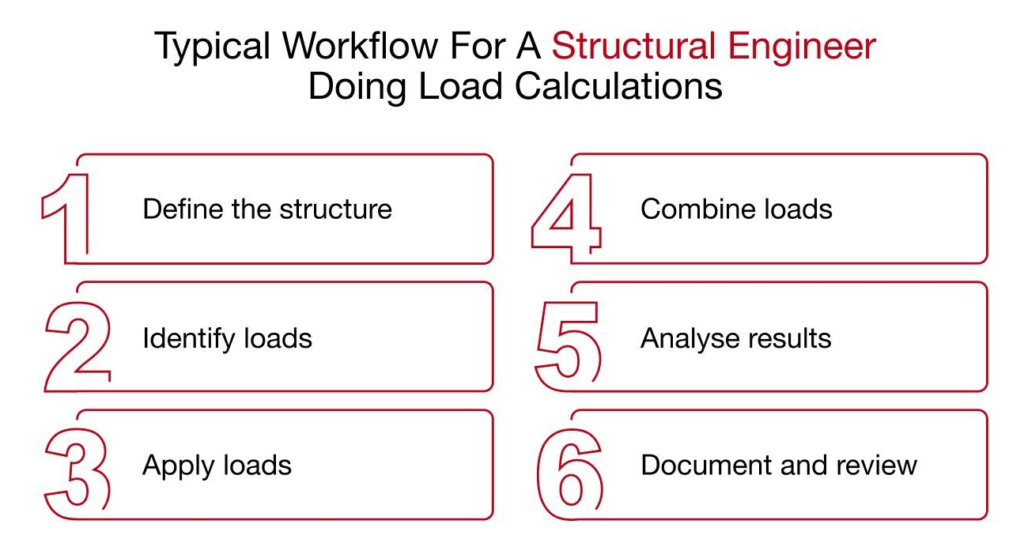
The important point is that Eurocode 3 is not simply a collection of equations. It is a systematic framework for understanding structural behavior and demonstrating adequate reliability.
Diagrams and Design Tables
Simplified Eurocode 3 design workflow
          STRUCTURAL REQUIREMENTS
                    │
                    ▼
             ACTIONS / LOADS
                    │
                    ▼
          STRUCTURAL ANALYSIS
                    │
                    ▼
          MEMBER INTERNAL FORCES
                    │
          ┌─────────┴─────────┐
          ▼                   ▼
     CROSS-SECTION         STABILITY
     RESISTANCE            CHECKS
          │                   │
          └─────────┬─────────┘
                    ▼
             SERVICEABILITY
                    │
                    ▼
              CONNECTIONS
                    │
                    ▼
          FABRICATION / ERECTION
                    │
                    ▼
              FINAL DESIGN
Major Eurocode 3 design considerations
| Category | Typical engineering question |
|---|---|
| Material | Is the selected steel suitable? |
| Geometry | Is the structural arrangement appropriate? |
| Resistance | Can the member carry its design actions? |
| Local stability | Can plate elements buckle locally? |
| Global stability | Can the member or frame become unstable? |
| Serviceability | Are deflections and vibrations acceptable? |
| Connections | Can forces safely transfer between members? |
| Durability | Will the structure perform over its intended life? |
| Execution | Can it realistically be fabricated and erected? |


Understanding stability visually
One of the most important ideas in steel engineering is that strength does not automatically mean stability.
A long, slender compression member can become unstable before the material reaches its nominal yield strength.
Similarly, an unrestrained beam can experience lateral-torsional buckling even when its bending resistance appears adequate from a simple bending check.
This is why structural steel design requires both resistance checks and stability checks.
Practical Examples
Example 1 — Warehouse column
Imagine a steel warehouse with a large roof.
The columns support roof loads and resist horizontal actions from wind and frame behavior.
A beginner might simply choose a large column based on axial load.
A professional design considers:
- Axial compression
- Bending
- Column length
- Restraint conditions
- Buckling behavior
- Cross-section classification
- Frame stability
- Connection behavior
The final section may therefore be governed by stability rather than simple material strength.
Example 2 — Office floor beam
An office floor beam carries permanent and imposed loads.
The engineer must consider both structural resistance and user comfort.
A beam that is strong enough but excessively flexible may be unsuitable.
Consequently, member selection can be controlled by:
strength + stability + stiffness + architectural requirements.
Example 3 — Industrial roof
A roof beam may appear simple, but its compression flange can become vulnerable to lateral-torsional buckling if adequate lateral restraint is not provided.
The engineer therefore evaluates the restraint system rather than assuming that the beam is laterally supported simply because it forms part of a roof.
Real-World Applications
Eurocode 3 principles are relevant to a wide range of steel construction.
Commercial buildings 🏢
Steel frames are frequently used for offices, shopping centers, schools, and other buildings where flexible floor layouts are valuable.
Industrial buildings 🏭
Warehouses and factories benefit from steel’s ability to create large clear spans.
Sports facilities 🏟️
Stadiums and sports halls often require long-span structural systems with carefully controlled deflection and stability.
High-rise construction
Steel framing can provide efficient load paths and rapid construction when combined with appropriate floor and stability systems.
Infrastructure
Eurocode 3 extends beyond ordinary buildings. The wider EN 1993 family includes specialized provisions for bridges, towers, tanks, silos, piling, crane-supporting structures, and other applications.
Common Mistakes
Treating Eurocode 3 as an isolated standard
A frequent beginner mistake is opening EN 1993-1-1 and attempting to design the entire structure from that document alone.
Steel design normally requires interaction with EN 1990, EN 1991, relevant material and execution standards, the applicable National Annex, and other Eurocode 3 parts where necessary.
Ignoring the National Annex
Eurocodes are European standards, but project-specific national provisions can influence the design parameters and recommended choices.
Always identify the National Annex applicable to the project location.
Checking strength but ignoring stability
This is one of the most serious conceptual mistakes.
A section can possess substantial material strength while having inadequate buckling resistance.
Assuming ideal restraint
A computer model may assume a member is laterally restrained, but the real structure must actually provide that restraint.
Forgetting serviceability
Excessive deflection or vibration can make an otherwise safe structure unacceptable.
Selecting sections without considering fabrication
The theoretically lightest section is not always the most economical solution once welding, connections, transportation, corrosion protection, and erection are considered.
Challenges and Solutions
| Challenge | Practical solution |
|---|---|
| Complex stability behavior | Build a clear structural model and identify possible buckling modes |
| Large number of design parameters | Maintain a structured calculation workflow |
| Different National Annexes | Confirm project jurisdiction before design |
| Higher-strength steel | Verify all relevant material and stability provisions |
| Complex geometry | Use appropriate structural analysis methods |
| Connection complexity | Coordinate member and connection design early |
| Construction-stage instability | Design temporary stability and erection sequence |
| Software dependence | Verify software assumptions with engineering judgment |
The second-generation Eurocode 3 development specifically includes changes aimed at simplifying and harmonizing aspects of design, including stability rules and analysis methods.
Case Study: Steel Warehouse Frame
Consider a hypothetical single-storey industrial warehouse.
The building has:
- Steel portal frames
- Long-span roof beams
- Steel columns
- Purlins
- Bracing
- Bolted connections
- Lightweight roof cladding
Stage 1 — Conceptual design
The engineer establishes the frame spacing, building height, roof arrangement, and stability system.
Stage 2 — Loading
Permanent roof loads, imposed actions, wind and other relevant actions are established according to the applicable loading provisions.
Stage 3 — Structural analysis
The frame is analyzed to determine the governing internal actions.
Stage 4 — Member design
Columns and rafters are checked for their relevant combinations of axial force, bending, shear and stability.
Stage 5 — Stability
The engineer investigates frame stability and individual-member buckling.
This is particularly important for the long-span rafters.
Stage 6 — Connections
The forces are transferred through the selected bolted and welded connection arrangements.
Stage 7 — Serviceability
Roof deflections and other applicable performance criteria are reviewed.
Stage 8 — Construction
The engineer verifies that the selected components can be fabricated, transported, lifted and erected safely.
The result is not merely a collection of individually adequate steel members. It is an integrated structural system.
Essential Tips for Students and Professionals
Learn structural behavior before memorizing clauses
Understanding why a beam buckles is more valuable than memorizing a buckling expression without understanding its physical meaning.
Draw the load path
Ask:
Where does the load enter the structure, and where does it finally reach the foundation?
This simple question exposes many conceptual errors.
Separate ULS and SLS thinking
Keep safety and usability checks conceptually distinct.
Understand buckling
Spend serious study time on:
- Flexural buckling
- Lateral-torsional buckling
- Local buckling
- Frame instability
These concepts appear repeatedly in steel design.
Do not blindly trust software
Structural software can perform calculations extremely quickly, but it cannot automatically correct an incorrect structural model.
Always understand:
- Boundary conditions
- Releases
- Restraints
- Load paths
- Effective lengths
- Analysis assumptions
Keep the National Annex visible
When working on a real project, establish the applicable National Annex before finalizing design parameters.
Use the latest applicable standard carefully
EN 1993-1-1:2022 is part of the second-generation Eurocode development. However, implementation and transition arrangements vary by country. For example, UK practice has specific transition arrangements between first- and second-generation Eurocodes.
Therefore, engineers should use the edition and National Annex required by the project’s governing authority or contract rather than automatically assuming that the newest edition is legally applicable.
Frequently Asked Questions
What is Eurocode 3?
Eurocode 3, or EN 1993, is the European family of standards for designing steel structures. It addresses resistance, serviceability, durability, stability, fire design and specialized steel applications.
What does EN 1993-1-1 cover?
EN 1993-1-1 provides general design rules for steel structures together with supplementary rules specifically applicable to buildings.
Is EN 1993-1-1 enough to design a complete steel building?
Usually, no. Steel building design normally requires interaction with EN 1990, EN 1991, the applicable National Annex, execution standards, connection provisions and other relevant Eurocodes.
What is cross-section classification?
Cross-section classification identifies how susceptible different parts of a steel section are to local buckling and determines the type of resistance and plastic behavior that can appropriately be used in design.
Why is buckling so important in steel design?
Steel members can become unstable before their material reaches its full strength. Slender compression members and inadequately restrained beams are particularly sensitive to instability.
What is the difference between ULS and SLS?
ULS focuses primarily on structural safety against failure, while SLS focuses on acceptable performance during normal use, including deflection, vibration and deformation.
Does Eurocode 3 apply only to buildings?
No. EN 1993 is a large family of standards covering many steel applications, including bridges, towers, tanks, silos, piling and crane-supporting structures.
Is the 2022 edition of EN 1993-1-1 the same as the older 2005 edition?
No. The 2022 edition belongs to the second generation and introduces significant changes, including expanded steel-grade applicability, revised stability provisions, changes to analysis methods and other technical developments.
Conclusion
Eurocode 3 – EN 1993-1-1 is fundamentally about understanding and controlling the behavior of steel structures. 🏗️
Successful design requires more than selecting a steel section with sufficient strength. Engineers must consider the complete structural system, including actions, material properties, cross-section classification, member resistance, buckling, global stability, serviceability, connections, fabrication and erection.
For students, the best learning strategy is to connect every design check to a physical structural behavior:
Load → Structural response → Failure mode → Verification → Safe design.
For professionals, the key is disciplined application of the complete Eurocode framework, including the relevant National Annex and project requirements.
The 2022 second-generation EN 1993-1-1 represents an important evolution of steel design practice, with expanded applicability and efforts to simplify and harmonize several design procedures.
Ultimately, good Eurocode 3 design is not about producing the largest or smallest steel member. It is about creating a safe, stable, serviceable, durable, economical, and constructible structural system. 🔩🏢⚙️
Engineering principle to remember:
Design the behavior, not just the section.