Design of Reinforced Concrete Foundations: Complete Guide for Students and Engineers 🏗️
Introduction 🏗️
A reinforced concrete foundation is one of the most important structural components in any building. It forms the critical connection between the superstructure and the ground, transferring loads safely into the soil while limiting excessive settlement, cracking, and structural movement.
A well-designed foundation does much more than simply support columns or walls. It must respond to dead loads, live loads, wind, seismic actions, soil pressure, groundwater, settlement, and construction conditions. For reinforced concrete foundations, the engineer must consider both the behavior of concrete and the behavior of embedded steel reinforcement.


The design process therefore combines structural engineering + geotechnical engineering + construction detailing. 🌍
For students, foundation design is an excellent way to understand how theoretical structural mechanics becomes a practical building system. For professional engineers, it is a discipline where small detailing decisions can have major consequences.
This article presents a practical introduction to the design of reinforced concrete foundations, from soil investigation and foundation selection to reinforcement detailing, construction quality, and real-world applications.
Background Theory
How a Foundation Transfers Load
The structural load generally follows a simple path:
Roof → Floors → Beams → Columns/Walls → Foundation → Soil
The foundation spreads the concentrated structural load over a larger area so that the resulting soil pressure remains within acceptable limits.
A column may carry a substantial load over a relatively small cross-sectional area. If that load were transferred directly to the ground, the soil could experience excessive pressure. A footing increases the contact area and distributes the load.
Concrete and Reinforcement Work Together
Concrete performs particularly well under compression, while reinforcing steel provides resistance where tensile stresses develop.
A reinforced concrete footing therefore behaves as a composite structural element.
The basic concept can be visualized as:
Concrete → compression + protection + stiffness
Steel reinforcement → tension + crack control + structural continuity
This interaction is fundamental to reinforced concrete foundation design. 🔩
Soil Is Part of the Structural System
A foundation cannot be designed correctly by looking only at concrete and reinforcement.
The engineer must understand:
- Soil bearing capacity
- Soil stiffness
- Expected settlement
- Differential settlement
- Groundwater conditions
- Soil expansion or shrinkage
- Frost effects in cold climates
- Potential erosion or scour
- Existing underground structures
- Site drainage
Consequently, foundation design is normally coordinated with a geotechnical investigation.
Definition
What Is a Reinforced Concrete Foundation?
A reinforced concrete foundation is a structural element made primarily from concrete and reinforcing steel that transfers building loads to the supporting ground or, in some cases, to piles or other deep foundation elements.
Depending on the structural arrangement and site conditions, foundations may include:
- Isolated footings
- Combined footings
- Strip or continuous footings
- Raft or mat foundations
- Pile caps
- Wall footings
- Grade beams
- Stepped foundations
What Makes a Foundation “Reinforced”?
A plain concrete footing relies primarily on concrete to resist structural actions.
A reinforced concrete footing incorporates steel reinforcement strategically positioned within the concrete to resist tensile stresses, bending effects, cracking, and other structural demands.
The reinforcement arrangement is not arbitrary. Bar diameter, spacing, location, anchorage, development, lap lengths, cover, and detailing must follow the structural design and applicable building code.
Types of Reinforced Concrete Foundations 🧱
Isolated Footings
An isolated footing supports a single column.
It is often economical when columns are sufficiently separated and the soil has adequate bearing capacity.
Typical shapes include:
- Square
- Rectangular
- Circular
- Stepped configurations
The reinforcement commonly forms a bottom reinforcement grid, although additional reinforcement may be required depending on the structural configuration.
Combined Footings
A combined footing supports two or more columns.
It becomes useful when columns are close together or when an exterior column is positioned near a property boundary.
The footing geometry is selected so that the soil pressure distribution remains acceptable.
Strip Foundations
Strip foundations support continuous walls or closely spaced structural elements.
They are common in:
- Masonry buildings
- Low-rise construction
- Load-bearing wall systems
- Some retaining-wall applications
Raft or Mat Foundations
A raft foundation consists of a large reinforced concrete slab supporting several columns and/or walls.
It can be advantageous where:
- Soil bearing capacity is relatively low
- Columns are closely spaced
- Individual footings would occupy a large percentage of the building footprint
- Settlement control is important


Step-by-Step Design of Reinforced Concrete Foundations 🔧
Step 1: Collect Structural Information
Start with the structural model and determine the forces transferred to the foundation.
Important information includes:
- Column dimensions
- Wall locations
- Axial loads
- Moments
- Shear forces
- Load combinations
- Building geometry
- Number of floors
- Structural system
- Wind and seismic effects where applicable
The foundation should be designed for the governing design conditions rather than a single simplified load.
Step 2: Obtain the Geotechnical Information
A foundation engineer needs reliable information about the supporting ground.
A geotechnical report may provide:
- Allowable or design soil pressure
- Soil classification
- Groundwater level
- Settlement parameters
- Soil layers
- Recommended foundation depth
- Excavation recommendations
- Frost considerations
- Chemical exposure information
Skipping this stage can lead to a foundation that appears structurally adequate but performs poorly because the soil behavior was misunderstood.
Step 3: Select the Foundation Type
Choose the foundation system according to:
Structural loads + soil conditions + site restrictions + economy + construction requirements
For example, a moderately loaded isolated column on competent soil may be suitable for an isolated footing.
A heavily loaded building on weak soil may require a raft or deep foundation solution.
Step 4: Establish the Preliminary Footing Size
The preliminary dimensions should provide sufficient contact area with the ground.
The engineer evaluates the expected soil pressure and checks whether the resulting distribution is compatible with the soil and structural requirements.
The footing should also be proportioned to avoid unnecessary eccentricity.
Step 5: Check Soil Pressure
Soil pressure is one of the most important foundation design checks.
The engineer considers:
- Average contact pressure
- Maximum contact pressure
- Minimum contact pressure
- Load eccentricity
- Overturning effects
- Uplift where relevant
A footing subjected to significant moment may develop a nonuniform soil pressure distribution.
Step 6: Determine the Required Thickness
Footing thickness is influenced by:
- Bending
- One-way shear
- Punching shear
- Anchorage requirements
- Concrete cover
- Constructability
A footing that is excessively thin may require too much reinforcement or fail a shear check.
A very thick footing may be structurally unnecessary and increase construction cost.
Step 7: Design the Reinforcement
The reinforcement must be positioned where tensile stresses are expected.
For many isolated footings, the principal reinforcement is located near the bottom because the footing bends under the upward soil reaction.
However, the actual arrangement depends on the foundation geometry, loading, column position, continuity, and governing code.
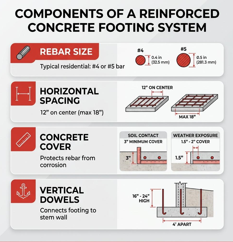
Typical detailing considerations include:
- Main reinforcement
- Secondary reinforcement
- Column starter bars
- Dowels
- Development length
- Lap splices
- Reinforcement spacing
- Concrete cover
- Bar supports
Step 8: Check Punching Shear
Punching shear is particularly important around columns.
Imagine the column trying to push through the footing. The surrounding concrete must provide enough resistance to prevent a localized failure mechanism.
This is why footing thickness and column dimensions are extremely important.
Step 9: Check One-Way Shear
The footing should also be checked for one-way shear near critical sections.
This check evaluates whether the concrete section can resist the shear associated with the soil reaction and applied structural loads.
Step 10: Detail the Drawing
The final foundation drawing should clearly identify:
- Footing dimensions
- Concrete grade
- Reinforcement grade
- Bar sizes
- Bar spacing
- Concrete cover
- Column position
- Starter bars
- Development lengths
- Section details
- Construction joints
- Levels and elevations
A design that cannot be clearly constructed is not a successful engineering design.


Comparison of Foundation Types
| Foundation Type | Typical Application | Main Advantage | Main Limitation |
|---|---|---|---|
| Isolated footing | Individual columns | Simple and economical | Not ideal for closely spaced columns |
| Combined footing | Two or more columns | Useful near boundaries | More complex geometry |
| Strip footing | Continuous walls | Simple load distribution | Limited for heavy concentrated loads |
| Raft foundation | Many columns/weak soil | Large load-distribution area | Higher concrete and reinforcement quantities |
| Pile foundation | Deep/weak surface soil | Transfers loads to deeper strata | More expensive and construction-intensive |
| Pile cap | Groups of piles | Connects piles to columns | Requires accurate pile positioning |
Diagrams & Engineering Tables 📐
Simplified Load Path
        COLUMN
          │
          ↓
   ┌─────────────┐
   │   FOOTING   │
   │  REINFORCED │
   │   CONCRETE  │
   └─────────────┘
     ↓ ↓ ↓ ↓ ↓
   SOIL REACTION
══════════════════
     SUPPORTING
       SOIL
Typical Isolated Footing Concept
             COLUMN
               ││
               ││
        ┌──────┴┴──────┐
        │              │
        │    FOOTING   │
        │              │
        └──────────────┘
      ═══════════════════
          SOIL LAYER
Important Design Checks
| Check | Main Question |
|---|---|
| Bearing pressure | Can the soil safely support the foundation? |
| Settlement | Will the foundation move excessively? |
| Bending | Is sufficient reinforcement provided? |
| One-way shear | Is the footing adequate against shear failure? |
| Punching shear | Is the column-to-footing region safe? |
| Sliding | Could horizontal forces move the foundation? |
| Overturning | Is the foundation stable under moments? |
| Uplift | Can the foundation resist upward forces? |
| Reinforcement detailing | Can the reinforcement develop its required strength? |
| Durability | Is the concrete adequately protected from the environment? |


Practical Examples 🏢
Example 1: Small Commercial Building
Consider a low-rise commercial building supported by reinforced concrete columns.
The geotechnical investigation indicates competent soil near the planned foundation level.
The engineer may select isolated footings for most internal columns. Each footing is proportioned according to its column load and the soil characteristics.
The reinforcement is arranged to resist bending caused by the soil reaction.
Example 2: Column Near a Property Boundary
Suppose an exterior column is positioned very close to a property line.
A conventional isolated footing might extend outside the permitted boundary.
A combined or strap footing can provide a better solution by coordinating the exterior column with another structural support.
Example 3: Weak Near-Surface Soil
Imagine a building where the upper soil layer has relatively poor bearing characteristics.
Individual footings could become very large.
The engineer may investigate a raft foundation because it spreads structural loads across a much larger area.
Example 4: Industrial Structure
An industrial building may experience substantial column loads combined with equipment vibration and horizontal forces.
The foundation design therefore requires closer coordination between structural, geotechnical, mechanical, and construction engineers.
Real-World Applications 🌍
Reinforced concrete foundations are used extensively in:
- Residential buildings
- Apartment buildings
- Office buildings
- Hospitals
- Universities
- Warehouses
- Factories
- Bridges
- Industrial facilities
- Data centers
- Parking structures
- Infrastructure projects
In regions with challenging ground conditions, the foundation solution may become one of the most technically demanding parts of the entire project.
In cold regions such as parts of Canada, the UK, and Northern Europe, frost and ground conditions require special attention.
In parts of the USA and Australia, expansive soils, settlement, drought-related ground movement, or site-specific geotechnical conditions can significantly influence foundation selection.
Common Mistakes ⚠️
Ignoring the Geotechnical Report
One of the biggest mistakes is designing the concrete foundation without understanding the soil.
Solution: Coordinate structural and geotechnical design from the beginning.
Incorrect Reinforcement Position
Steel reinforcement placed too close to the soil or moved from its specified position can compromise the intended structural behavior and durability.
Solution: Use appropriate spacers and reinforcement supports.
Insufficient Concrete Cover
Concrete cover protects reinforcement from environmental exposure and contributes to durability and fire resistance.
Solution: Follow the applicable structural code and project specifications.
Poor Column-to-Footing Connection
Starter bars must be correctly positioned and properly developed.
Solution: Check bar diameter, spacing, anchorage, development, and alignment before concrete placement.
Treating Every Footing as Identical
Two footings in the same building may have completely different loads or ground conditions.
Solution: Design each foundation according to its actual structural and geotechnical requirements.
Poor Construction Documentation
A technically correct calculation can still produce construction errors if the drawings are unclear.
Solution: Provide readable plans, sections, bar marks, schedules, dimensions, levels, and notes.
Challenges & Solutions
| Challenge | Practical Solution |
|---|---|
| Weak soil | Investigate raft, ground improvement, or deep foundation alternatives |
| High groundwater | Provide appropriate temporary and permanent water-control measures |
| Restricted site | Consider combined or specially proportioned foundations |
| Heavy column loads | Evaluate larger footings, rafts, or piles |
| Differential settlement | Improve soil investigation and foundation coordination |
| Congested reinforcement | Optimize detailing and construction sequence |
| Aggressive environment | Specify suitable concrete durability requirements |
| Difficult excavation | Coordinate temporary works and excavation stability |
| Seismic forces | Follow the governing seismic and structural requirements |
| Construction variability | Use inspection, testing, and quality-control procedures |
Case Study: Foundation Selection for a Multi-Storey Office Building 🏢
Consider a hypothetical six-storey office building planned on an urban site.
The structural engineer estimates significant column forces, while the geotechnical investigation identifies moderately competent soil near the proposed foundation level.
Initial Concept
The first concept uses isolated footings.
During preliminary design, several internal footings become relatively large because of the column loads. Some exterior columns also create geometric restrictions.
Engineering Review
The design team compares:
- Isolated footings
- Combined footings
- A raft foundation
- Deep foundations
The comparison considers structural performance, soil behavior, excavation requirements, reinforcement quantities, concrete volume, construction duration, and project cost.
Final Concept
Suppose the team selects a raft foundation after determining that it provides a more practical load-distribution system for the site.
The raft is then designed for:
- Column loads
- Wall loads
- Soil reactions
- Bending
- Shear
- Punching shear
- Settlement behavior
- Reinforcement requirements
- Construction sequencing
The lesson is important:
The cheapest foundation is not necessarily the one with the least concrete.
The best solution is the one that provides an appropriate combination of safety, serviceability, durability, constructability, and economy.
Essential Tips for Foundation Design 🧠
For Students
- Understand soil mechanics before attempting advanced footing design.
- Learn the difference between bearing capacity and settlement.
- Understand how soil reaction produces bending in a footing.
- Practice reading structural foundation drawings.
- Learn reinforcement detailing—not just calculations.
- Study punching and one-way shear carefully.
- Compare different foundation systems rather than designing only one type.
For Professional Engineers
- Review the geotechnical report carefully.
- Confirm design loads and load combinations.
- Coordinate column and foundation geometry.
- Check both strength and serviceability.
- Pay attention to reinforcement anchorage.
- Review construction tolerances.
- Consider groundwater and durability.
- Inspect reinforcement before concrete placement.
- Avoid unnecessary reinforcement congestion.
- Follow the project-specific governing code.
A Simple Engineering Rule 🏗️
Good foundation design = Structural safety + Soil compatibility + Constructability + Durability + Economy
Ignoring any one of these can create problems later.
FAQs
What is the purpose of reinforcement in a concrete footing?
Reinforcement provides tensile resistance, helps control cracking, and allows the footing to resist bending and other structural actions that concrete alone cannot efficiently handle.
Why is reinforcement commonly placed near the bottom of an isolated footing?
The soil pushes upward against the footing while the column load acts downward. This produces bending behavior that commonly places the principal tensile region near the bottom of an isolated footing. The exact arrangement must be determined from the structural analysis.
What is punching shear in foundation design?
Punching shear is a localized shear failure mechanism that can develop around a concentrated load, such as a column. It is an important design check for isolated footings and rafts.
Is a larger footing always safer?
No. Increasing footing dimensions may reduce soil pressure, but it does not automatically solve every structural problem. Thickness, bending, shear, settlement, reinforcement, eccentricity, and constructability must also be considered.
What foundation is best for weak soil?
There is no universal answer. Possible solutions include larger spread foundations, raft foundations, ground improvement, or deep foundations. The appropriate choice depends on the geotechnical investigation and structural requirements.
How important is concrete cover?
Concrete cover is extremely important for protecting reinforcement and achieving the required durability and fire performance. The required cover depends on the applicable code and exposure conditions.
Which standards are commonly relevant to reinforced concrete foundation design?
The governing standard depends on the project location. Engineers may work with standards such as ACI 318, Eurocode 2, BS/EN standards, CSA A23.3, AS 3600, or national/local structural and foundation codes.
Can foundation design be done without a soil investigation?
For significant engineering projects, relying on assumptions instead of appropriate geotechnical information is poor practice. Foundation dimensions and type depend directly on ground conditions, so geotechnical input is fundamental.
Conclusion 🏁
The design of reinforced concrete foundations is a multidisciplinary engineering task that connects structural behavior with real ground conditions.
A successful foundation begins with understanding the soil and structural loads. The engineer then selects an appropriate foundation type, establishes suitable dimensions, evaluates soil pressure and settlement, designs for bending and shear, and develops reinforcement details that can actually be constructed.
The process can be summarized as:
Investigate → Select → Size → Analyze → Reinforce → Detail → Inspect → Construct 🔄
For students, foundation design provides an excellent opportunity to connect structural analysis, reinforced concrete design, and soil mechanics.
For practicing engineers, the key lesson is even broader: a foundation is not simply a block of concrete beneath a column—it is the engineered interface between the building and the ground.
When structural calculations, geotechnical information, reinforcement detailing, construction quality, and durability are considered together, reinforced concrete foundations can provide the reliable load-transfer system required for buildings and infrastructure throughout the USA, UK, Canada, Australia, and Europe. 🏗️🌍