Computational Structural Analysis and Finite Element Methods: A Complete Beginner-to-Professional Guide for Modern Engineering 🏗️⚙️📊
Introduction 🚀
Computational Structural Analysis has revolutionized modern engineering by allowing engineers to predict how structures behave before they are built. Instead of relying solely on hand calculations, engineers now use powerful computer algorithms to simulate loads, stresses, strains, vibrations, thermal effects, and material behavior with exceptional accuracy.
Finite Element Method (FEM) is the foundation of nearly every commercial structural simulation software, including ANSYS, Abaqus, COMSOL Multiphysics, SAP2000, STAAD.Pro, LS-DYNA, and Autodesk Simulation.
Whether designing a skyscraper in New York, an aircraft wing in Europe, a bridge in Canada, or offshore platforms in Australia, finite element analysis has become an indispensable engineering tool.


Today, computational structural analysis is used throughout the engineering lifecycle:
- 🏢 Building design
- 🌉 Bridge engineering
- ✈️ Aerospace structures
- 🚗 Automotive crash simulations
- ⚡ Wind turbines
- 🚢 Ships and offshore platforms
- 🚄 Railway infrastructure
- 🛰️ Spacecraft components
The combination of mathematical models and high-speed computing enables engineers to reduce costs, improve safety, and accelerate product development.
Background Theory 📚
Structural engineering is fundamentally based on mechanics.
When external forces act on a structure, the structure responds through:
- Internal stresses
- Internal strains
- Deformations
- Rotations
- Vibrations
Classical engineering methods solve these problems using differential equations derived from:
- Newton’s Laws
- Hooke’s Law
- Equilibrium equations
- Compatibility equations
- Constitutive relationships
For simple beams and frames, these equations can be solved analytically.
However, modern engineering structures are often:
- Highly complex
- Curved
- Nonlinear
- Composite
- Large-scale
- Subjected to multiple loading conditions
Analytical solutions become impossible.
This is where Computational Structural Analysis becomes essential.
Instead of solving the entire structure simultaneously, the structure is divided into thousands—or even millions—of very small elements.
Each element behaves according to mathematical equations.
The computer then assembles all element equations into one global system.
This process forms the basis of the Finite Element Method.
Definition 📖
Computational Structural Analysis is the use of numerical methods and computer algorithms to determine the behavior of engineering structures under different loading conditions.
Finite Element Method (FEM) is a numerical technique that divides a complex structure into many small interconnected elements so that engineers can accurately calculate stress, displacement, strain, temperature, vibration, and other physical responses.
Its primary objective is to approximate the real behavior of structures with high accuracy while minimizing computational cost.
Understanding the Finite Element Method Step by Step 🔍
Step 1 — Create the Geometry 📐
Every analysis begins with a geometric model.
The geometry may represent:
- Beam
- Plate
- Shell
- Solid
- Truss
- Frame
Modern CAD software exports models directly into FEM software.
Step 2 — Select Material Properties 🧱
Typical properties include:
- Young’s Modulus
- Poisson Ratio
- Density
- Yield Strength
- Thermal Conductivity
- Plastic Properties
Material accuracy directly affects simulation accuracy.
Step 3 — Generate the Mesh 🔲
The geometry is divided into many small elements.
These elements are connected through nodes.
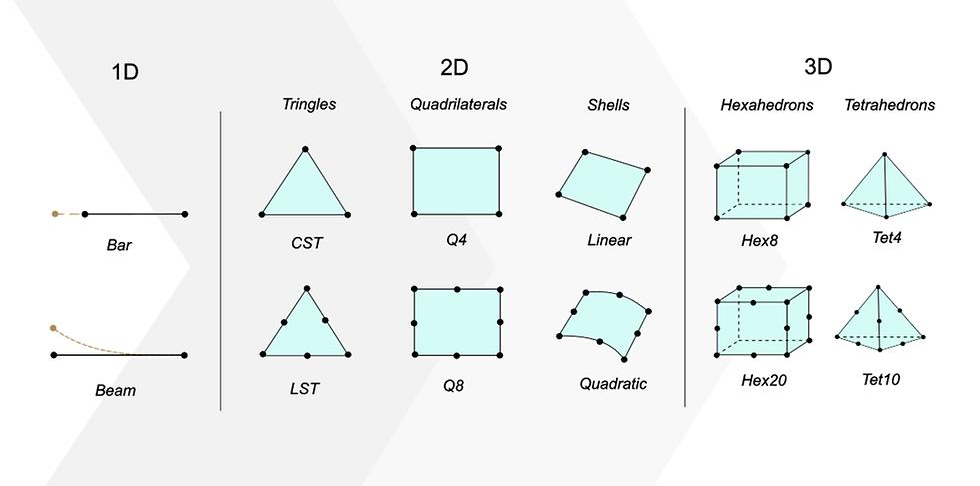
Common element types include:
- Triangular
- Quadrilateral
- Tetrahedral
- Hexahedral
A finer mesh generally increases solution accuracy but also increases computational time.
Step 4 — Apply Boundary Conditions 🔒
Boundary conditions define how the structure is constrained.
Examples include:
- Fixed support
- Roller support
- Hinged support
- Symmetry
- Elastic support
Without proper constraints, the model cannot produce meaningful results.
Step 5 — Apply Loads ⚡
Loads may include:
- Point loads
- Distributed loads
- Wind loads
- Earthquake loads
- Thermal loads
- Pressure
- Gravity
- Dynamic forces
Step 6 — Solve the Equations 💻
The software assembles the global stiffness matrix.
It then solves:
- Displacements
- Rotations
- Stresses
- Strains
- Reaction forces
Powerful numerical solvers perform millions of calculations within seconds.
Step 7 — Interpret Results 📊
Typical output includes:
- Stress contours
- Displacement contours
- Safety factors
- Reaction forces
- Mode shapes
- Buckling modes


Comparison ⚖️
| Feature | Classical Structural Analysis | Finite Element Analysis |
|---|---|---|
| Geometry | Simple | Very Complex |
| Accuracy | Moderate | Very High |
| Manual Calculation | Yes | No |
| Computer Required | Rarely | Always |
| Complex Materials | Difficult | Easy |
| Dynamic Analysis | Limited | Excellent |
| Thermal Analysis | Difficult | Built-in |
| Large Structures | Challenging | Efficient |
Diagrams and Tables 📈
Typical FEM Workflow
| Stage | Purpose |
|---|---|
| CAD Model | Create geometry |
| Material Assignment | Define material behavior |
| Meshing | Divide into finite elements |
| Boundary Conditions | Restrict movement |
| Load Application | Apply forces |
| Numerical Solver | Compute response |
| Post-Processing | Visualize results |
Common Element Types
| Element | Typical Use |
|---|---|
| Beam | Bridges |
| Truss | Towers |
| Plate | Floor slabs |
| Shell | Aircraft bodies |
| Solid | Machine parts |
| Axisymmetric | Pressure vessels |
Common Analysis Types
| Analysis | Purpose |
|---|---|
| Static | Constant loads |
| Dynamic | Time-varying loads |
| Modal | Natural frequencies |
| Harmonic | Vibrations |
| Thermal | Heat transfer |
| Buckling | Stability |
| Nonlinear | Plastic deformation |
| Fatigue | Life prediction |


Examples 🏗️
Example 1: Steel Beam
An engineer analyzes a simply supported beam carrying a distributed load.
The FEM software calculates:
- Maximum stress
- Maximum deflection
- Support reactions
- Safety factor
Example 2: Aircraft Wing ✈️
The wing experiences:
- Lift
- Drag
- Fuel weight
- Turbulence
Finite element analysis predicts structural deformation during flight.
Example 3: High-Rise Building 🏢
Simulation evaluates:
- Wind response
- Earthquake resistance
- Floor deflections
- Column stresses
Example 4: Car Crash 🚗
Automotive companies simulate:
- Impact forces
- Passenger safety
- Airbag deployment
- Structural collapse
before manufacturing a physical prototype.
Real-World Applications 🌍
Finite element analysis is widely used across engineering disciplines.
Civil Engineering
- Bridges
- Buildings
- Dams
- Stadiums
- Tunnels
Mechanical Engineering
- Engines
- Gearboxes
- Bearings
- Pressure vessels
- Turbines
Aerospace Engineering
- Aircraft wings
- Fuselages
- Rocket structures
- Satellite frames
Biomedical Engineering
- Artificial joints
- Dental implants
- Bone simulations
- Heart valves
Energy Industry
- Wind turbines
- Nuclear reactors
- Offshore platforms
- Pipelines
Manufacturing
- Injection molding
- Metal forming
- Welding simulations
- Additive manufacturing
Common Mistakes ❌
Many beginners make avoidable errors that reduce simulation accuracy.
Poor Mesh Quality
An irregular mesh can produce inaccurate stress concentrations.
Incorrect Boundary Conditions
Improper supports often create unrealistic deformation.
Unrealistic Material Properties
Using incorrect elastic modulus or density leads to misleading results.
Ignoring Mesh Convergence
One mesh size is rarely sufficient.
Engineers should refine the mesh until results stabilize.
Misinterpreting Stress Peaks
Stress singularities near sharp corners should not always be treated as physical failures.
Forgetting Units
Mixing SI and Imperial units is a frequent source of serious mistakes.
Challenges and Solutions 🛠️
| Challenge | Solution |
|---|---|
| Long computation time | Use adaptive meshing |
| Large memory requirements | High-performance computing |
| Poor convergence | Improve mesh quality |
| Contact instability | Refine contact definitions |
| Nonlinear material issues | Incremental loading |
| Complex geometry | Geometry simplification |
Case Study 🏢
Bridge Deck Optimization
A transportation engineering firm was tasked with redesigning a highway bridge deck.
Initial Design
Problems included:
- Excessive steel consumption
- High construction cost
- Large deflection
Computational Analysis
Engineers developed an FEM model containing over 600,000 elements.
The model included:
- Vehicle loading
- Wind loading
- Thermal expansion
- Dynamic traffic effects
Optimization
Multiple design iterations reduced unnecessary material while maintaining structural safety.
Final Results
- ✅ 15% lower steel usage
- ✅ 12% lower construction cost
- 📊 Improved fatigue life
- ✅ Smaller maximum deflection
- ✅ Compliance with international design standards
The project demonstrated how computational structural analysis can improve both safety and cost efficiency.
Essential Tips 💡
- 📌 Start with a simple model before adding complexity.
- 📌 Verify geometry carefully.
- 📊 Use consistent engineering units.
- 📌 Perform mesh convergence studies.
- 📌 Validate simulations with theoretical calculations whenever possible.
- 📊 Check reaction forces for equilibrium.
- 📌 Understand the physical meaning of every result.
- 📌 Never rely solely on software without engineering judgment.
- 📊 Document assumptions for future review.
- 📌 Keep software updated and learn solver limitations.
Frequently Asked Questions ❓
What is Computational Structural Analysis?
It is the numerical analysis of structures using computer algorithms to predict stress, strain, deformation, vibration, and structural performance.
Why is the Finite Element Method so popular?
Because it can solve engineering problems that are impossible or extremely difficult using analytical equations alone.
Which industries use FEM?
Civil, aerospace, automotive, mechanical, biomedical, marine, energy, manufacturing, and many other engineering industries.
Does a finer mesh always produce better results?
Not necessarily. While finer meshes often improve accuracy, they also increase computational cost. Engineers should perform mesh convergence studies to find an efficient balance.
What software is commonly used for structural analysis?
Popular tools include ANSYS, Abaqus, COMSOL Multiphysics, SAP2000, STAAD.Pro, LS-DYNA, Autodesk Simulation, and NASTRAN.
Is FEM only for structural engineering?
No. The method is also used for thermal, electromagnetic, fluid flow, acoustic, and multiphysics simulations.
Can beginners learn finite element analysis?
Yes. A solid understanding of mechanics, mathematics, and material behavior provides an excellent foundation. Modern software also offers intuitive interfaces that help beginners build practical skills.
Conclusion 🎯
Computational Structural Analysis and the Finite Element Method have transformed engineering by enabling accurate virtual testing before construction or manufacturing begins. From bridges and skyscrapers to aircraft, automobiles, medical devices, and renewable energy systems, FEM helps engineers improve safety, optimize designs, reduce costs, and shorten development cycles.
For students, mastering FEM strengthens core knowledge in mechanics, numerical methods, and structural behavior. For practicing engineers, it is an essential professional skill that supports innovation, compliance with design standards, and informed decision-making. As computing power and simulation technologies continue to evolve, computational structural analysis will remain at the forefront of modern engineering, empowering professionals worldwide to design safer, smarter, and more efficient structures.