300 Electronic Projects for Inventors with Tested Circuits: A Practical Handbook for Electronics Students, Engineers, and Makers
Introduction
Electronics becomes much easier to understand when theory is transformed into something that actually lights, moves, measures, switches, communicates, or responds. ⚡🔧 Instead of studying resistors, capacitors, transistors, diodes, sensors, and microcontrollers only as isolated components, practical projects allow learners to see how these elements cooperate as a complete engineering system.
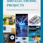
300 Electronic Projects for Inventors with Tested Circuits by Arsath Natheem S. is presented as a practical collection for innovators, engineering students, electronics enthusiasts, and hobbyists. The 2018 edition is listed as a 306-page independently published book and includes project ideas involving fundamental components, Arduino, Raspberry Pi, LEDs, transistors, ICs, PCBs, and other electronics concepts.


The important engineering lesson is not simply to reproduce a circuit. A good project teaches you to understand → calculate → assemble → measure → troubleshoot → improve. That workflow is useful whether you are building a university prototype, an embedded device, an automation system, or an experimental circuit at home.


This article explores the engineering principles behind large collections of electronic projects and explains how beginners and experienced engineers can turn project ideas into reliable prototypes.
Background Theory
Electronic projects are essentially controlled systems in which electrical energy and information move between different components.
At the most basic level, voltage creates the electrical potential that drives current through a circuit. Ohm’s law provides one of the most useful relationships:
V = I × R
where:
- V = voltage in volts (V)
- I = current in amperes (A)
- R = resistance in ohms (Ω)
Power is equally important:
P = V × I
A resistor may therefore perform several jobs: limiting current, establishing a voltage, creating a bias condition, or converting electrical energy into heat.
Capacitors behave differently. Their stored energy is related to:
E = ½CV²
where C represents capacitance and V represents voltage.
Diodes introduce directional behavior, while transistors can act as electronic switches or amplifiers. Integrated circuits combine multiple functions into compact packages. Microcontrollers then add programmability, allowing a physical circuit to respond dynamically to sensors and software.
From Components to Systems
A simple LED circuit can contain only a power source, resistor, and LED. A smart environmental monitor, however, may combine:
Sensor → Signal conditioning → Microcontroller → Software → Display/Communication → Actuator
This progression is one reason practical project collections are valuable: they allow learners to gradually move from individual components toward complete embedded systems.
Analog and Digital Electronics
Analog circuits process continuously varying signals such as:
- temperature
- sound
- light intensity
- voltage
- pressure
Digital circuits generally operate using discrete logic states such as HIGH and LOW.
Modern projects frequently combine both. For example, a temperature sensor can generate an analog signal, an ADC can convert it into a digital value, and a microcontroller can use that value to control a fan.
Definition
A practical electronic project can be defined as a designed electrical or electronic system created to perform a specific measurable function.
The function could be extremely simple:
Turn an LED on when a switch is pressed.
Or considerably more advanced:
Measure temperature and humidity, process the readings, display them, and transmit the information wirelessly.
The concept behind 300 Electronic Projects for Inventors with Tested Circuits is therefore broader than simply learning circuit diagrams. Its stated scope includes fundamental electronic components and practical projects intended for students, hobbyists, innovators, and electronics enthusiasts.
What Makes a Project Useful?
A strong engineering project normally contains five elements:
- Input — sensor, switch, microphone, keypad, etc.
- Processing — transistor, op-amp, IC, Arduino, Raspberry Pi, etc.
- Output — LED, motor, buzzer, display, relay, or communication interface.
- Power system — battery, USB, regulated supply, or another source.
- Verification — measurements demonstrating that the design operates correctly.
Step-by-Step Explanation: From Idea to Working Circuit
The most effective way to approach hundreds of project ideas is not to build them randomly. Use a repeatable engineering process. 🧠⚙️

Step 1: Define the Function
Write a single sentence describing what the circuit should do.
For example:
“The LED should illuminate when the light level falls below a selected threshold.”
This immediately identifies the likely requirements:
- light sensor
- threshold circuit or microcontroller
- LED
- current-limiting resistor
- power supply
Step 2: Identify the Inputs and Outputs
Create a simple block diagram:
Light → LDR → Controller → LED
For a more sophisticated project:
Sensor → ADC → Microcontroller → Decision Algorithm → Driver → Load
This approach prevents unnecessary components from being added before the basic architecture is understood.
Step 3: Select Components
Choose components according to electrical requirements rather than appearance.
For an LED circuit, determine:
- supply voltage
- LED forward voltage
- desired LED current
- resistor value
A simplified calculation is:
R = (V_supply − V_LED) / I_LED
For example, if a 5 V supply drives an LED with approximately 2 V forward voltage at 10 mA:
R = (5 − 2) / 0.01 = 300 Ω
A nearby standard resistor value can then be selected according to the desired operating current and component tolerances.
Step 4: Build the Prototype
A solderless breadboard is ideal during early development because components can be rearranged without permanently soldering them.
A basic Arduino LED experiment, for example, uses an LED and a series resistor. Practical Arduino tutorials commonly use this arrangement to demonstrate breadboard construction and circuit fundamentals.
Step 5: Test Before Adding Complexity
Never build an entire complicated circuit at once.
Test:
Power → Sensor → Controller → Output
one stage at a time.
Measure voltage with a multimeter before connecting expensive components.
Step 6: Document the Results
Record:
- supply voltage
- measured current
- sensor readings
- component values
- software version
- observed faults
- modifications
This turns a hobby experiment into an engineering project.
Comparison
Different project categories teach different engineering skills.
| Project Type | Main Skills | Typical Difficulty | Typical Applications |
|---|---|---|---|
| LED circuits | Current limiting, polarity | ⭐ | Indicators |
| Transistor circuits | Switching, biasing | ⭐⭐ | Drivers, alarms |
| 555 timer projects | Timing, oscillation | ⭐⭐ | Delays, pulse generators |
| Sensor circuits | Measurement, conditioning | ⭐⭐⭐ | Monitoring |
| Arduino projects | Programming + electronics | ⭐⭐⭐ | Automation |
| Raspberry Pi projects | Linux + electronics | ⭐⭐⭐⭐ | IoT, data logging |
| PCB projects | Layout, manufacturing | ⭐⭐⭐⭐ | Finished products |
| Embedded systems | Hardware + firmware | ⭐⭐⭐⭐⭐ | Professional products |
The project collection is particularly relevant because its description covers basic components as well as Arduino and Raspberry Pi-based embedded projects.
Discrete Circuits vs Microcontroller Projects
A transistor circuit may perform a function without software.
A microcontroller-based design can implement the same function using firmware.
Discrete approach:
Sensor → Transistor → Load
Microcontroller approach:
Sensor → ADC → MCU → Software → Transistor → Load
The second approach offers greater flexibility, but also introduces programming, firmware debugging, timing, and software-related failure modes.
Diagrams & Tables


Generic Electronics Project Architecture
        ┌───────────────┐
        │   POWER UNIT  │
        └───────┬───────┘
                │
                ▼
        ┌───────────────┐
        │    SENSOR     │
        └───────┬───────┘
                │
                ▼
        ┌───────────────┐
        │ SIGNAL / ADC  │
        └───────┬───────┘
                │
                ▼
        ┌───────────────┐
        │ CONTROLLER    │
        │ MCU / IC      │
        └───────┬───────┘
                │
        ┌───────┴────────┐
        ▼                ▼
   ┌─────────┐      ┌──────────┐
   │ DISPLAY │      │  DRIVER  │
   └─────────┘      └────┬─────┘
                         │
                         ▼
                     ┌───────┐
                     │ LOAD  │
                     └───────┘
Useful Component Relationships
| Component | Primary Function | Important Parameter |
|---|---|---|
| Resistor | Limits/sets current | Ω |
| Capacitor | Stores charge/filtering | F |
| Diode | One-way conduction | Forward voltage |
| LED | Visual output | Forward current |
| Transistor | Switching/amplification | Current/gain |
| Relay | Electrical isolation/switching | Coil voltage |
| 555 IC | Timing/oscillation | Timing R and C |
| Arduino | Programmable control | I/O, ADC |
| Raspberry Pi | Computing/control | GPIO, interfaces |
Examples
Example 1: LED Indicator
One of the best introductory projects is a simple LED indicator.
5 V → Resistor → LED → GND
The resistor protects the LED by controlling current. The exact resistance should be selected from the supply voltage, LED forward voltage, desired current, and practical component tolerances.
This seemingly simple project teaches polarity, Ohm’s law, current flow, breadboard connections, and measurement.
Example 2: Automatic Night Light
Replace the manual switch with an LDR.
Light intensity → LDR voltage divider → Comparator/MCU → LED
As ambient light decreases, the sensor voltage changes. The circuit can then switch the LED.
This project introduces sensing and threshold detection.
Example 3: Temperature Monitor
A temperature sensor can be connected to a microcontroller.
Temperature → Sensor → ADC → Arduino → Display
The engineer must consider sensor accuracy, ADC resolution, calibration, noise, and power consumption.
Example 4: Environmental Monitoring
A more advanced design could combine:
- temperature sensor
- humidity sensor
- gas sensor
- light sensor
- microcontroller
- display
- data logging
A real-world sensor breadboard may contain multiple sensors connected through jumper wires to a controller, illustrating how individual measurement modules can be combined into a larger monitoring system.
Real-World Application
The principles represented by practical electronics projects appear throughout engineering.
Industrial Automation
Sensors detect:
- temperature
- pressure
- position
- vibration
- current
- proximity
Controllers process those signals and activate motors, valves, relays, or alarms.
Smart Buildings
Electronic projects can evolve into:
Motion detection + lighting control + temperature monitoring + wireless communication
The same fundamental ideas can be applied to energy-management systems.
Automotive Electronics
Automotive systems rely heavily on sensors, microcontrollers, drivers, communication buses, and power electronics.
Robotics
A small robot combines multiple engineering disciplines:
Sensors + control algorithm + motor driver + motors + power system
The electronics project becomes a miniature control system.
Education and Research
Arduino-based experimental platforms have also been used for teaching scientific concepts because inexpensive microcontroller hardware makes it possible to connect physical measurements with computation.
Common Mistakes
Ignoring Component Polarity
Electrolytic capacitors, LEDs, diodes, transistors, and ICs can have specific orientations.
A reversed component can cause malfunction or damage.
Connecting an LED Without Current Limiting
An LED should generally be operated with appropriate current control rather than connected directly to a voltage source.
Using the Wrong Supply Voltage
A circuit designed for 5 V should not automatically be connected to 12 V.
Always check the voltage rating of every component.
Forgetting Common Ground
When two modules communicate electrically, they often require a shared reference unless the interface is intentionally isolated.
Building Too Much at Once
If a 30-component circuit fails, finding the problem can be difficult.
Build functional blocks separately.
Trusting a Schematic Without Verification
A circuit diagram is not automatically a guarantee that your physical implementation will work.
Check:
- component values
- pinouts
- supply requirements
- polarity
- tolerances
- current limits
Challenges & Solutions
| Challenge | Likely Cause | Engineering Solution |
|---|---|---|
| LED does not illuminate | Reversed LED/open connection | Check polarity and continuity |
| MCU resets | Power instability | Improve supply and decoupling |
| Sensor readings fluctuate | Noise | Filtering, shielding, averaging |
| Transistor overheats | Excess current | Check load and dissipation |
| Circuit works intermittently | Loose breadboard connection | Inspect wiring |
| Motor causes resets | Electrical noise/current surge | Separate supply and add suppression |
| Wrong sensor readings | Calibration error | Compare against reference |
| Circuit works on bench but fails in enclosure | Thermal/layout effects | Test under realistic conditions |
Debugging Method
Use the divide-and-test strategy.
Instead of asking:
“Why doesn’t my whole circuit work?”
Ask:
“Does the power stage work?”
Then:
“Does the sensor produce the expected signal?”
Then:
“Does the controller receive that signal?”
Finally:
“Does the output driver respond correctly?”
This dramatically reduces troubleshooting time.
Case Study: Building an Automatic Light Controller
Consider a student designing an automatic lighting system.
Stage 1 — Requirement
The light should turn on when the environment becomes dark.
Stage 2 — Sensor
An LDR is used to detect ambient illumination.
Stage 3 — Signal Processing
The LDR and resistor create a voltage divider:
V_out = V_CC × R₂ / (R₁ + R₂)
The changing voltage represents the light condition.
Stage 4 — Decision
A comparator or microcontroller determines whether the voltage has crossed the selected threshold.
Stage 5 — Driver
If the load requires more current than the controller can safely provide, a transistor or MOSFET driver can be used.
Stage 6 — Output
The driver activates an LED array, lamp, or other suitable low-voltage load.
Stage 7 — Engineering Improvement
The basic system can then be upgraded with:
- adjustable sensitivity
- delay timing
- ambient-light calibration
- display
- battery monitoring
- wireless communication
- data logging
This illustrates the central philosophy of project-based electronics: one simple circuit can become the foundation of a much more sophisticated engineering system.
Essential Tips
🔧 Start with low-voltage DC projects. They are safer and easier to measure.
📐 Calculate before connecting. Estimate voltage, current, resistance, and power.
🔬 Use a multimeter. Measurement is more reliable than guessing.
🧠 Understand the component, not just the wiring. Know why each component exists.
⚡ Respect power ratings. A resistor, transistor, regulator, or PCB trace can overheat when overloaded.
📝 Document every successful experiment. Record circuit values and measured results.
🧩 Modify working projects. Change one parameter at a time and observe the effect.
💻 Combine hardware and software gradually. First verify the circuit, then introduce firmware.
🔋 Separate sensitive and high-current loads when necessary. Motors and relays can introduce electrical noise.
🌍 Adapt circuits to your region and application. Supply standards, mains voltage, regulations, and component availability can differ between countries.
The latter point is especially important for projects involving mains electricity. Some reader feedback concerning this particular book notes that certain AC circuits may use European-style 230 V/50 Hz assumptions, making regional adaptation important for users elsewhere. Mains-voltage experiments should only be performed by appropriately qualified people using compliant equipment and procedures.
FAQs
Is this book suitable for electronics beginners?
Yes. Its stated audience includes beginners, engineering students, hobbyists, innovators, and electronics enthusiasts, while its subject matter progresses from basic components toward practical embedded projects.
What components should I learn first?
Start with resistors, capacitors, diodes, LEDs, transistors, switches, potentiometers, voltage regulators, and basic ICs. Then move toward sensors and microcontrollers.
Do I need Arduino to learn electronics?
No. Arduino is useful, but fundamental electronics can be learned through completely discrete circuits. Arduino becomes particularly valuable when projects require programmable decision-making.
Are breadboards suitable for professional products?
Breadboards are excellent for prototyping and experimentation, but finished products generally require a properly designed PCB or another appropriate permanent assembly method.
How do I troubleshoot a circuit that does not work?
Begin with the power supply. Then check component orientation, continuity, wiring, expected voltages, signal paths, and output stages. Test one functional block at a time.
Why are resistors important in electronic projects?
Resistors control current and establish voltages. They are fundamental for LED protection, transistor biasing, voltage dividers, pull-up/pull-down networks, filtering, and signal conditioning.
Can project ideas be turned into engineering products?
Absolutely. A simple prototype can become a product after additional work involving reliability, PCB design, enclosure design, firmware, testing, safety, regulatory compliance, manufacturing, and cost optimization.
Is a tested circuit automatically production-ready?
No. A prototype that works on a laboratory bench still requires engineering validation. Production designs need tolerance analysis, thermal testing, fault analysis, EMC considerations, environmental testing, safety assessment, and appropriate compliance testing.
Conclusion
300 Electronic Projects for Inventors with Tested Circuits represents a project-oriented approach to learning electronics: start with fundamental components, understand their electrical behavior, assemble practical circuits, measure their performance, and progressively introduce programmable controllers and embedded technologies.
The book’s published descriptions emphasize a large collection of practical project ideas covering components such as resistors, capacitors, diodes, transformers, transistors, LEDs, ICs, PCBs, Arduino, and Raspberry Pi.
⚡ For beginners, the greatest value of this approach is that it transforms abstract equations into visible results. For engineering students, projects provide a bridge between classroom theory and laboratory implementation. For professionals and experienced makers, project collections can become sources of design inspiration and starting points for experimentation.
The most important lesson, however, is not the number 300. It is the engineering workflow behind every successful circuit:
Idea → Theory → Calculation → Prototype → Measurement → Debugging → Optimization → Application ⚡🔧📐
Once you learn to follow that process, a resistor and LED can become more than a classroom experiment—they can become the first building blocks of an automation system, sensor network, robot, embedded controller, or intelligent electronic product.